There are 2 different known ways to drive them that are widely known:
– SPI epapers, can be driven with this popular interface that is supported from Arduino, to a wide variety of MCUs
– Parallel epapers also called einks like the ones that are used in Kindle & another e-readers
Let’s start with the most easy to drive that also needs less GPIOs.

SPI controllers (inside the epaper display)
There are at least 2 quite well known brands, one is UltraChip and another is Solomon, and both require a boost helper circuit. They usually come with a 24 pin FPC connector that is connected with pins facing up towards the PCB.
Taken as an example EPD controller SSD1677 from Solomon we can see this essential characteristics:
– Resolution: 960 source outputs; 680 gate outputs
– VGH: 15V to 20V; VGL: -15V (Voltage adjustment step: 500mV)
That if I understand correctly means that this drivers take “control over the EPD matrix” directly. They have usually a 1-bit mono dual RAM that is used for BLACK and RED (or 2 different gray layers) and that is why their gray capabilities are limited to only 4 grays in some models.


Benefits:
– They drive the panel efficiently taking control over the matrix with a controller that is designed to use minimal power
– They also generate the voltages with the need of an external PCB circuit, they allow via SPI commands to regulate this voltages + VCOM
– You can send the full or partial framebuffer per SPI and then just keep on with your Firmware or even deepsleep, the controller will take care to deliver the gate/source signals to the EPD and maintain power until the update finishes
– They use less IOs, typically 3 for SPI (CLK,SDI,DC), and 2 other signals (Busy, Reset, CS) and just need a 3V3 as VCC power.
– Very good contrast both in Black/White as in Black/ Red/ White. Not sure if it’s because their controllers have the perfect waveform or simply because is a different built than the parallel ones.
Contraints:
– You cannot skip rows. If you draw a single black point at the end of the buffer, it will draw white all over, till it sends the black dot
– You don’t have full grayscale control as in parallel mode, some displays have maximum 3 shade of grays and it’s not really to display nice looking photography. I guess at the beginning the target was to be able to simply draw stuff like for the Supermarket price tags that we can see they are all over in big chain nowadays.
– Another fact is that RAM is usually expensive so this controllers have only 1bit RAM that is only large enough to keep 2 buffers of the display. They are designed for mass production so costs are an important factor.
SPI helper tools and external circuit
The image below was stolen from an SPI vendor website but all of them have their own version that does exactly the same, has a small DC-DC boost voltage helper in the other side, and redirect the SPI & signals to the right pins in the 24 pin FPC.
In case you want to use it in your own PCB: Circuit proved to work here actually that is a full KiCad PCB that can be on top of a ESP32 Tinypico.

Parallel drive
This displays can be found in eBay or Aliexpress and as sold as replacements for broken e-reader displays. The unknown hero that researched on how to drive them initially using an STM32 was Petteri Aimonen from Finland, which not only drove them, probably for the first time in any hobbyist MCU but also documented it. It seems the cold finnish winters are excellent to stay at home tinkering:

As you can see in Petteri’s image this is a block diagram where the EPD matrix was taken over by two big shift registers. For technical details you can actually check the website I referenced before since he explains it much better than me, but actually it summarizes to the following:
– Gate driver is the responsible for selecting one row, and only that is active once at a time.
– Source driver is the one that receives the 2-bit data stream per pixel and latches the incoming row to the output effectively triggering each pixel MOSFET (and making the ink float up with -15V or down with +15V)
This is done in a few passes in order to get full black, monochrome mode is the fastest and is called MODE_DU. Usually with 6 to 10 passes is full black already (More passes, means more time and consumption)
There is also gray mode that is usually called MODE_GC16 or similar, that is a matrix that has more passes defined usually 30 to 38 or even more, and has:
MODE, Temperature range, Gray1 and Gray2 matrix | action array
Sadly this is given by Eink to display buyers in a strange undocumented format called WBF (Waveform not to be mistaken with similar sound extension)
But is not the end of the world. This are just electronic pulses that are given to each pixel according to your framebuffer to arrive to the gray destination.
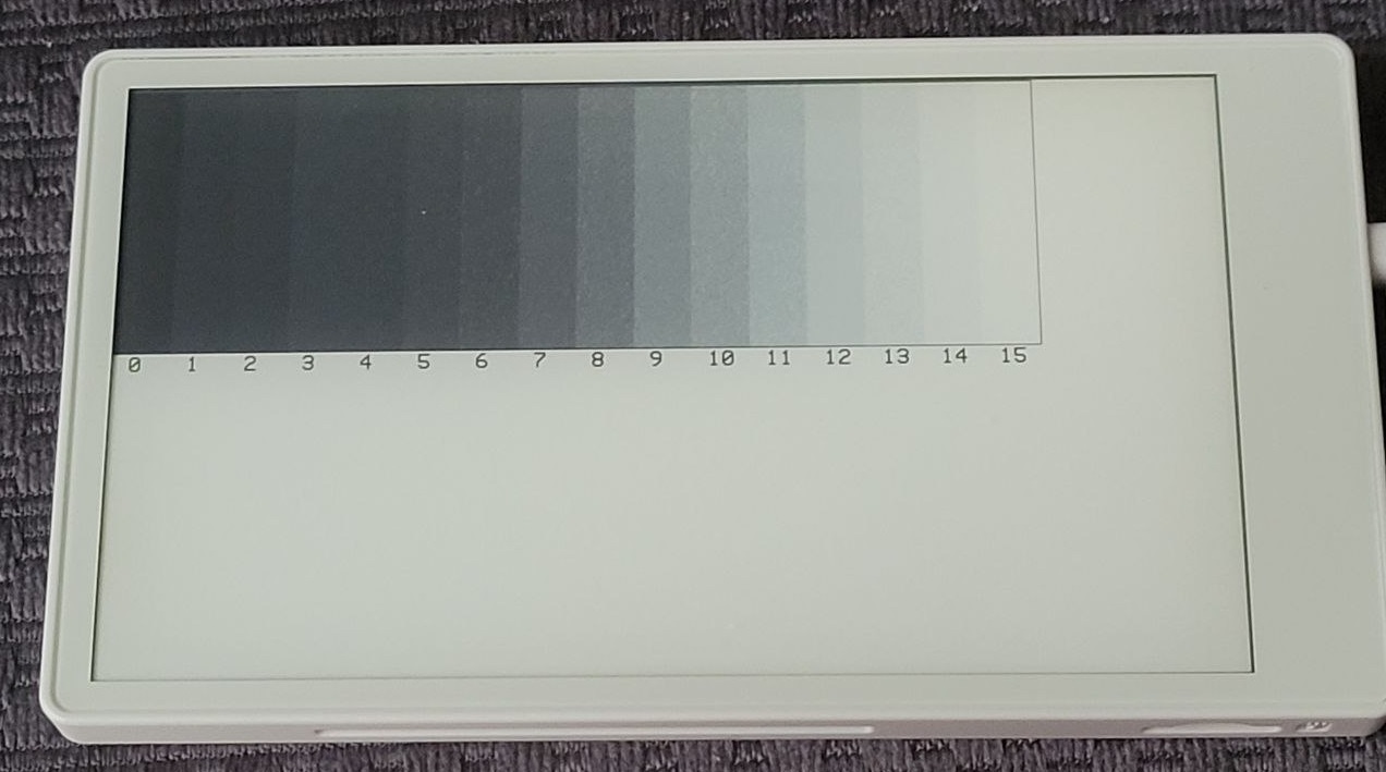
For example let’s take mode and temperature out, and let’s assume we go always from white to target gray in fast MODE_DU and room temperature in 8 passes.
As an example:
Gray level 0 = WHITE, 15 = BLACK (16 levels)
and action: 2 = lighten, 1 = darken, 0 = no action (No voltage applied)
This is all theoretical as an example since usually there are more phases used.
Gray 1  | Gray 2 | Actions (8 as example)
     0    15       1,1,1,1,1,1,1,1

And if we would do the reverse action:

Gray 1  | Gray 2 | Actions (8 as example)
     15    0       2,2,2,2,2,2,2,2

Or we want a middle gray in GC16 slower more (usually longer passes)
      0    6       0,0,0,0,0,1,1,1
So after Petteri published his research a few years later around 2018 Valentin Roland though about using an Espressif MCU to do a similar thing creating a widely known library called EPDiy. Note that Espressif is really good enough to drive parallel but is really terrible with power consumption, I guess it’s a good tradeoff only if you will use BLE or WiFi since then you have everything on the same chip. But it comes for a price and it’s that while driving the display and sending the parallel data + triggering quite a lot of signals (Similar to those used in LCDs & other displays like hsync, vsync and output enable) the ESP32 is working at max capacity that means at least in S3 it consumes around 100 to 140 mA per hour.
Here you can see more detailed consumption examples on the v7 epdiy board.
Actually is OK to make a photo application that every few hours downloads a JPG from the internet or things that are only from “time to time” updated. But use it constantly or with LVGL and you will have a constant 150 mA consumption that eats your battery like Donuts.
Benefits:
- Full granular control, meaning you can skip rows, make several passes getting full black or grayscales
- Almost universal way to drive it. Except of the annoying different connector types all parallel seem to be industry like, even from different brands, all seem to share same signals
The cursed part - Every different display size has a different FPC connector (only standard seems that most face down connection pins) being 6” 34 pins, 9.7” 33 pins, 13.3” 39 pins and the list goes on and on, being a nightmare dream for anyone intending to make an universal driver PCB
- The waveform 2 bit stream format from Eink has no documentation, no one really knows how it is, and even having some parsers online most open source libraries will end up doing the grays “by hand”. We need to thank Eink for being so transparent protecting their business.
- High consumption. Unless you can do parallel with a very low consumption MCU this will consume all the time while it’s sending the parallel data and signals at full speed.
- Not such a great contrast as the SPI displays (In certain models) probably because the gray matrix is not perfect for the temperature is being updated, VCOM is not regulated as it should be, and variety of other factors. But I must say that the modern 16-bit Einks sold by Waveshare look as good and close to SPI counterparts. You might have different luck when buying random displays from Aliexpress.
There is an additional issue with epdiy that I never liked and it’s how the gray matrix is built. It was thought at the beginning to make a WBF parser but at the end the files were really updated by hand and the format is really hard to get.
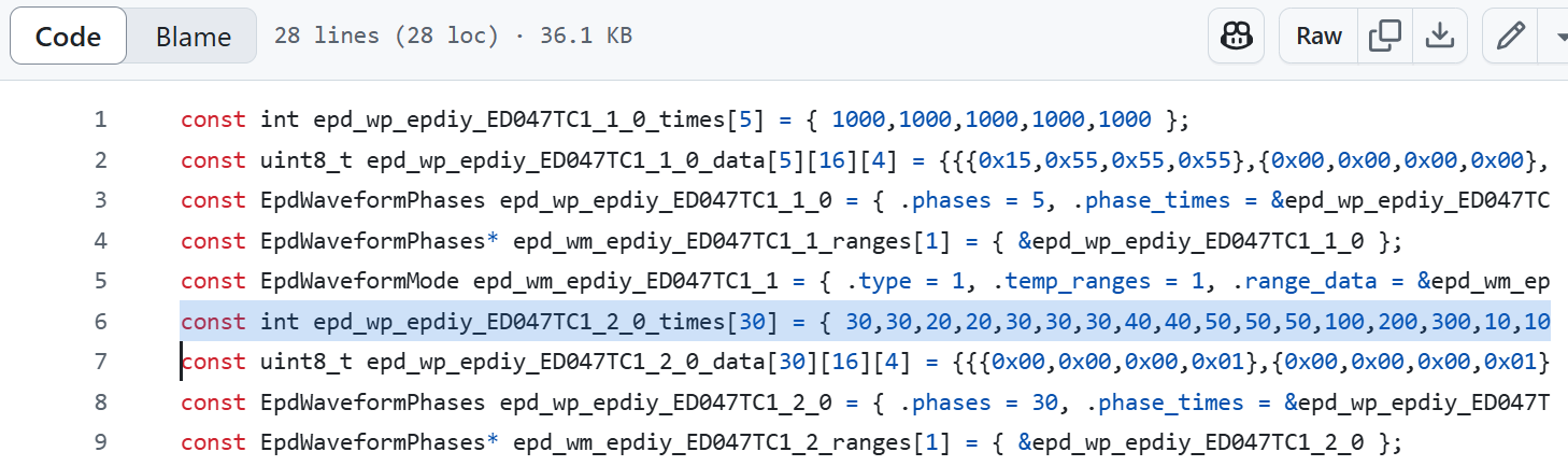
In the older ESP32-WROVER version there where different timings used for each pass. But in the v7 version that uses new Espressif LCD module this timings are ignored. All this plus the cryptic data inside the Phases made really hard to adapt new display grayscales. Which resulted in many issues about “waveforms” and how to solve this.
At the end of 2024 I teamed up with my long-time colleague and friend Larry Bank to change this and make a library from the ground up, that uses an human format for the display grays matrix. This coupled with the fact that Larry has a wide experience moving pixels, doing GFX, and code optimization for different companies will hopefully be an efficient and powerful alternative of epdiy. Additionally he has already a very good SPI library called bb_epaper and the idea is that GFX functions will be the same, enabling you swiftly switch your project from SPI eink to a parallel counterpart without much hassle other than changing initialization.
I cannot reveal anything more at this point but I would like to comment that I will help with the library, the testing and my latest addiction, the hardware part of the things, using all the experience recollected in last years of work in the field. The only piece of code I want to show just is how he resolved the gray matrix shown above in a human understandable way that anyone will be able to edit for his target display:
[c]
// 38 columns by 16 rows. From white (15) to each gray (0-black to 15-white)
const uint8_t u8GrayMatrix[] = {
/* 0 */	    0,  0,  0,  2,  2,  2,  2,  0,  0,  0,  0,  0,  1,  1,  1,  1,  1,  1,  1,  1,  1,  1,  1,  1,  1,  1,  1,  1,  1,  1,  1,  1,  1,  1,  1,  1,  1,  0,
/* 1 */	    2,	2,	2,	2,	2,	2,	2,	2,	2,	2,	2,	0,	1,	1,	1,	1,	1,	1,	1,	1,	1,	1,	1,	1,	1,	1,	1,	1,	1,	1,	1,	1,	1,	1,	1,	1,	1,  0,
/* 2 */		0,	0,	2,	2,	2,	2,	2,	2,	2,	2,	2,	2,	2,	0,	0,	1,	1,	1,	1,	1,	1,	1,	1,	1,	1,	1,	1,	1,	1,	1,	1,	1,	1,	1,	1,	1,	1,  0,
/* 3 */		0,	0,	0,	1,	2,	2,	2,	2,	2,	2,	2,	2,	2,	2,	2,	0,	0,	1,	1,	1,	1,	1,	1,	1,	1,	1,	1,	1,	1,	1,	1,	1,	1,	1,	1,	1,	0,  0,
/* 4 */		0,	0,	0,	0,	0,	2,	2,	2,	2,	2,	2,	2,	2,	2,	2,	2,	2,	2,	1,	1,	1,	1,	1,	1,	1,	1,	1,	1,	1,	1,	1,	1,	1,	1,	1,	1,	1,  0,
/* 5 */		0,	0,	0,	1,	1,	1,	1,	1,	1,	1,	1,	1,	0,	0,	2,	2,	2,	2,	2,	2,	2,	2,	2,	2,	2,	2,	1,	1,	1,	1,	1,	1,	1,	1,	1,	1,	0,  0,
/* 6 */		0,	1,	1,	1,	1,	1,	1,	1,	1,	1,	1,	1,	1,	1,	2,	2,	2,	2,	2,	2,	2,	2,	2,	2,	2,	2,	2,	2,	2,	1,	1,	1,	1,	1,	1,	1,	1,  0,
/* 7 */		0,	1,	1,	1,	1,	1,	1,	1,	1,	1,	1,	1,	1,	1,	1,	1,	2,	2,	2,	2,	2,	2,	2,	2,	2,	2,	2,	2,	2,	2,	2,	1,	1,	1,	1,	1,	1,  0,
/* 8 */		0,	1,	1,	1,	1,	1,	1,	1,	1,	1,	1,	1,	1,	1,	1,	1,	2,	2,	2,	2,	2,	2,	2,	2,	2,	2,	2,	2,	2,	2,	2,	1,	1,	1,	1,	1,	0,  0,
/* 9 */		0,	1,	1,	1,	1,	1,	1,	1,	1,	1,	1,	1,	1,	1,	1,	1,	1,	2,	2,	2,	2,	2,	2,	2,	2,	2,	2,	2,	2,	2,	2,	2,	2,	1,	1,	1,	1,  0,
/* 10 */	0,	1,	1,	1,	1,	1,	1,	1,	1,	1,	1,	1,	1,	1,	1,	1,	1,	1,	2,	2,	2,	2,	2,	2,	2,	2,	2,	2,	2,	2,	2,	2,	2,	2,	1,	1,	1,  0,
/* 11 */	0,	1,	1,	1,	1,	1,	1,	1,	1,	1,	1,	1,	1,	1,	1,	1,	1,	1,	1,	2,	2,	2,	2,	2,	2,	2,	2,	2,	2,	2,	2,	2,	2,	2,	1,	1,	0,  0,
/* 12 */	0,	0,	0,	0,	0,	0,	0,	0,	0,	1,	1,	1,	1,	1,	1,	1,	1,	1,	1,	1,	1,	1,	2,	2,	2,	2,	2,	2,	2,	2,	2,	2,	2,	2,	1,	0,	0,  0,
/* 13 */	0,	1,	1,	1,	1,	1,	1,	1,	1,	1,	1,	1,	1,	1,	1,	1,	1,	1,	2,	2,	2,	2,	2,	2,	2,	2,	2,	2,	2,	2,	2,	2,	2,	2,	2,	1,	0,  0,
/* 14 */	0,	1,	1,	1,	1,	1,	1,	1,	1,	1,	1,	1,	1,	1,	1,	1,	1,	1,	2,	2,	2,	2,	2,	2,	2,	2,	2,	2,	2,	2,	2,	2,	2,	2,	2,	1,	2,  0,
/* 15 */	1,	1,	1,	1,	1,	1,	1,	1,	1,	1,	1,	1,	1,	1,	1,	1,	2,	2,	1,	1,	2,	2,	2,	2,	2,	2,	2,	2,	2,	2,	2,	2,	2,	2,	2,	2,	0,  0
};
[/c]
That’s a cool matrix to see. It is exactly how a human representation of this grayscale waveform should be designed to make it easy so it’s possible to update it and experiment till you get the right grays that you expect. Popular boards like those from epdiy v7 (S3), LilyGO and M5 epaperS3 will be supported.
Actually all new boards supporting LCD Module should be supported provided the right GPIOs are configured.
It will be really easy to switch your firmware and adapt it to different boards and target displays. I’m excited about what the future will bring and hope this becomes a really popular and widely used library:
https://github.com/bitbank2/FastEPD/

Please try it if you have any compatible hardware and give it a Github ☆ if you like it!
