-
On driving Eink displays
There are 2 different known ways to drive them that are widely known:– SPI epapers, can be driven with this popular interface that is supported from Arduino, to a wide variety of MCUs– Parallel epapers also called einks like the ones that are used in Kindle & another e-readers Let’s start with the most easy…
-

Low power ULP C6 PCB
This was a great idea from my friend Larry Bank. But what is the ULP and how can we benefit from it?In Espressif own words: And what are the possibilities to use this small ULP processor while the rest of main CPU sleeps using the smallest possible power consumption? With this points in mind the…
-

Testing touch on small SPI epaper displays
Our now IDF ver. 5 compatible touch component FT6X36 is ready to be tested. There are two affordable models that I would like to cover in this post. First one is the 400×300 FT6336 from Good Display, we can see this one in action (2nd video, 1st had still wrong Waveform) It’s important to know…
-
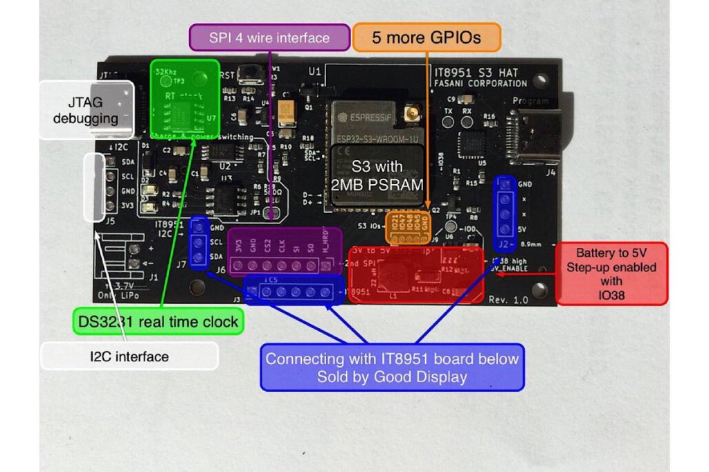
New Cinwrite SPI HAT for IT8951 parallel epaper controllers
At the moment only available in Tindie Fasani Corporation store this PCB mission is to provide: This Cinwrite PCB is open source Hardware that you can explore and even adapt to your needs. The price is 45 USD since I only made 5 and otherwise it will be impossible to cover the costs. But it…
-
LVGL to design UX interfaces on epaper
lv_port_esp32-epaper is the latest successful attempt to design UX in C using Espressif ESP32.If you like the idea please hit the ★ in my repository fork.What is LVGL? LVGL stands for “Light and Versatile Graphics Library” and allows you to design an object oriented user interface in supported devices. So far it supports mostly TFT…
-
Repurposing the MIDI protocol to control Led Matrixes
Meet Remora-matrix a project that started with the idea to sniff MIDI messages and make simple visuals on a LED-Matrix. Our previous Firmware Remora was intended to receive short commands from ORCΛ and make very simple Neopixels animations on addressable LEDs stripes (WS2812B like)With this one I decided to go a step further and make…
-
Using WiFi epapers to showcase digital art
Recently I stepped upon superrare.co that is a marketplace to collect and trade unique digital artworks. This and the fact that I follow Josh Katzenmeyer that is a member of this network made more aware of the fact I enjoy watching this artworks very much and got me interested about it. My idea is very…
-

Testing the new ESP32-S2
I got one ESP32-S2 Saola board and I will be making some tests on this repository: https://github.com/martinberlin/ESP32-S2 ESP32-S2 integrates a rich set of peripherals, with 43 programmable GPIOs which can be flexibly configured to provide USB OTG, LCD interface, camera interface, SPI, I2S, UART, ADC, DAC and other common functionality. ESP32-S2 provides the optimal HMI…
-

Arduino-esp32 course – Espressif is on the www WebServer vs HttpClient – Chapter 4
Chapter 4 introduces code examples to make a server in ESP32
-
Arduino-esp32 course – General-purpose input/output (GPIO) – Chapter 3
I want to state here that I’m not an electronics engineer and I know the basics only after years of tinkering and because I use to soldier PCBs for my father since I’m 8 or so. So if there is anything that is not correctly explained just comment and I will try to document it…
-
Subscribe
Subscribed
Already have a WordPress.com account? Log in now.
