-
New product and service launched: sensoria
sensoria.cat a device that will monitor your working day every half an hour to monitor CO2, temperature and humidity. At the end of the day the logs are read by an AI agent that stores that information and analyses it, comparing it to all the week data, delivering a daily report. This includes a dashboard,…
-
On the pursuit of a lower deepsleep consumption
Sadly even if I tried hard, it was very challenging if not mission impossible to get a deepsleep of 10 uA, eventhough in the MCU datasheet might say that it consumes as low as 1 uA when it’s on deepsleep.And why is that?For a variety of reasons all quite hard to grasp. But the most…
-
On driving Eink displays
There are 2 different known ways to drive them that are widely known:– SPI epapers, can be driven with this popular interface that is supported from Arduino, to a wide variety of MCUs– Parallel epapers also called einks like the ones that are used in Kindle & another e-readers Let’s start with the most easy…
-
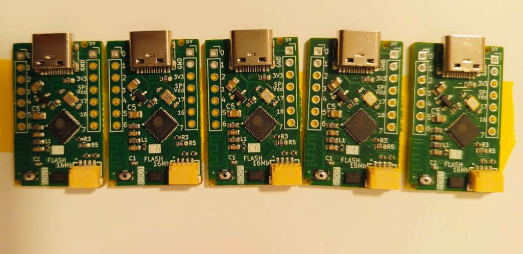
External Flash IC test on ESP32C6
In last board we send to fabrication the C6 ULP project I’ve failed miserably. Why?The board routing and schematics was Ok! But I’ve wrongly mistaken the ESP32C6 MCU using a 40 pin QFN that does not come with built in flash.You can find the open source KiCad files in this repository.Sadly that is the bad…
-

Low power ULP C6 PCB
This was a great idea from my friend Larry Bank. But what is the ULP and how can we benefit from it?In Espressif own words: And what are the possibilities to use this small ULP processor while the rest of main CPU sleeps using the smallest possible power consumption? With this points in mind the…
-
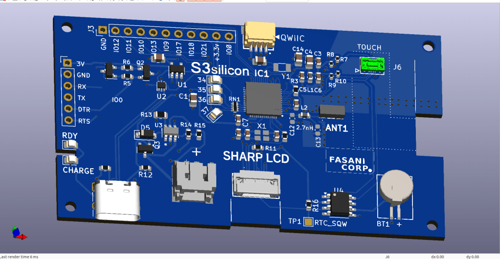
SHARP Controller LCD based on ESP32S3
The evolution of a simple C3 controller board into a full fledged ESP32S3 “Silicon only” small PCB that can control 400×240 LCDs and all their smaller models.First LCD controller I designed was a small clock size 128×128 pixels sharp LCD inspired by my friend Larry Bank who also likes this display technology. The evolution that…
-

Kindle paperwhite ESP32S3 controller
This is the resume of the previous entries where we custom modified epdiy version 7 into a custom PCB to control initially a Eink Kaleido display. In latest release we also modified slightly the Schematics to add a second touch model: TMA340 / TMA445 that is often found in the Kindle ED060XC3 also codenamed paperwhite…
-
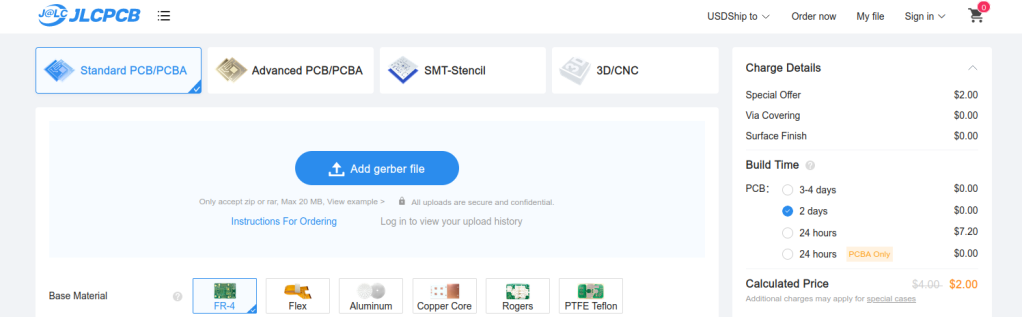
Sending boards to fabrication in JLCPCB using their PCB Assembly service
In this entry we are going to add some instructive videos on how we prepare fabrication files in order to send them to fabrication in JLCPCB using their PCBA service. In this 3 videos I show what is my personal approach to prepare fabrication files to send a PCB design to JLCPCB. Including the BOM…
-
Making an epdiy v7 Kaleido clone – Routing – part II
In Part I of this series we described how to take an existing KiCad open source repository, fork it, and start making updates to customize the PCB.This PCB will be ultimately sent to fabrication using our trusted service of JLCPCB using their PCB Assembly service. My mission in this PCB project is to make a…
-
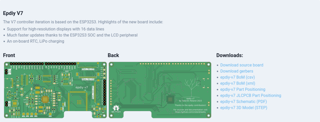
Making a epdiy v7 Kaleido clone – part I
In this post we are going to clone the epdiy v7 Hardware repository and make a custom version to control a Eink Kaleido 6 inches display.The existing epdiy v7 can control this epaper already but we want to make a PCB clone specifically for this display, removing other connectors and adding additional ones for Touch…
-
Subscribe
Subscribed
Already have a WordPress.com account? Log in now.
