-
On driving Eink displays
There are 2 different known ways to drive them that are widely known:– SPI epapers, can be driven with this popular interface that is supported from Arduino, to a wide variety of MCUs– Parallel epapers also called einks like the ones that are used in Kindle & another e-readers Let’s start with the most easy…
-

Low power ULP C6 PCB
This was a great idea from my friend Larry Bank. But what is the ULP and how can we benefit from it?In Espressif own words: And what are the possibilities to use this small ULP processor while the rest of main CPU sleeps using the smallest possible power consumption? With this points in mind the…
-
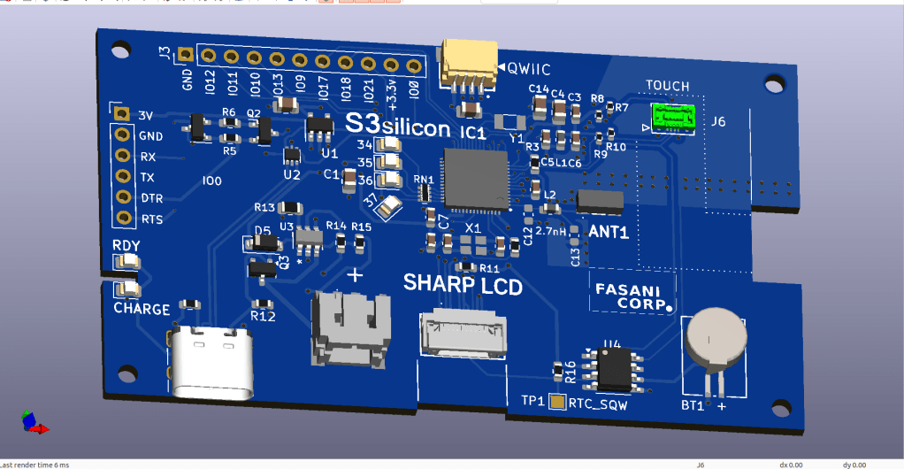
SHARP Controller LCD based on ESP32S3
The evolution of a simple C3 controller board into a full fledged ESP32S3 “Silicon only” small PCB that can control 400×240 LCDs and all their smaller models.First LCD controller I designed was a small clock size 128×128 pixels sharp LCD inspired by my friend Larry Bank who also likes this display technology. The evolution that…
-

Arduino-esp32 course – Espressif is on the www WebServer vs HttpClient – Chapter 4
Chapter 4 introduces code examples to make a server in ESP32
-
Arduino-esp32 course – General-purpose input/output (GPIO) – Chapter 3
I want to state here that I’m not an electronics engineer and I know the basics only after years of tinkering and because I use to soldier PCBs for my father since I’m 8 or so. So if there is anything that is not correctly explained just comment and I will try to document it…
-

PlatformIO: An alternative to Arduino IDE and a complete ecosystem for IoT
As an introduction I would like to make clear that I’m not a C++ advanced coder or IoT professional, I do this just because it’s a challenge, and because it’s a lot of fun compared to my 9 hrs/5 days a week web developer doing PHP and Admin panels for clients in Germany. Two months…
-
Subscribe
Subscribed
Already have a WordPress.com account? Log in now.
