-
On driving Eink displays
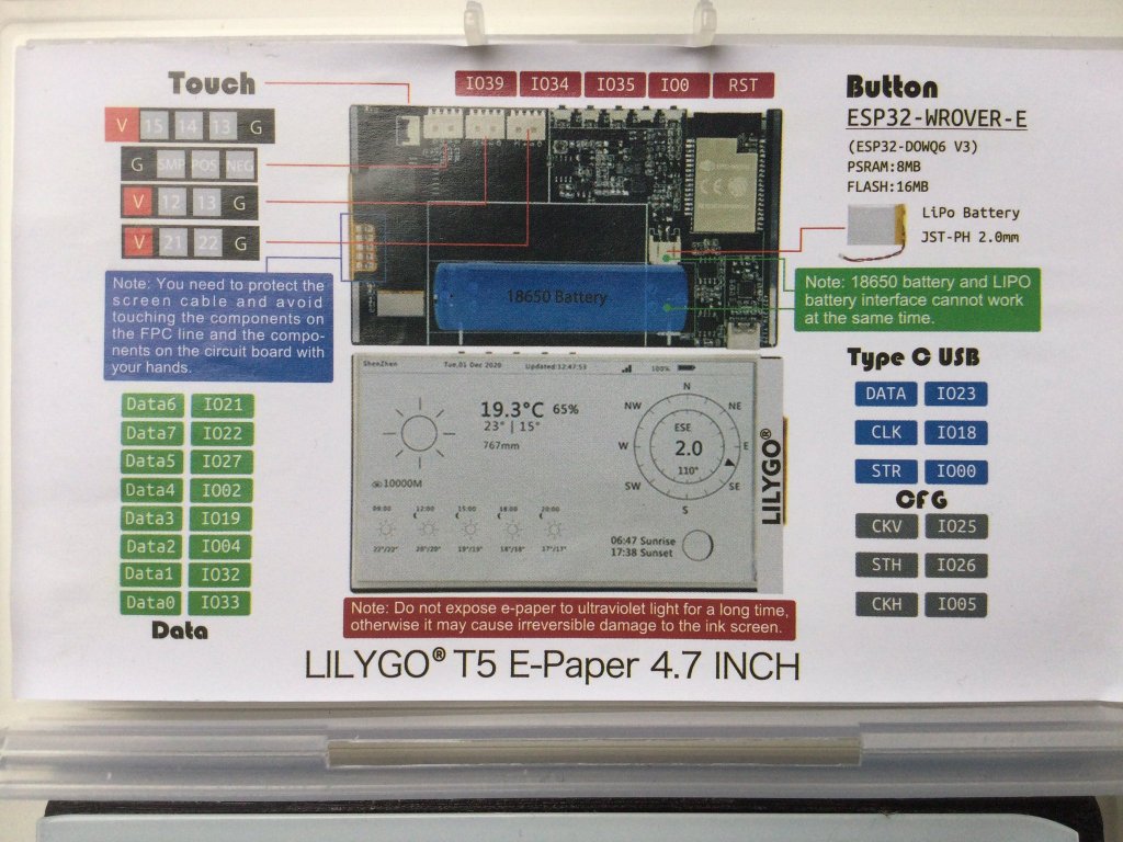
There are 2 different known ways to drive them that are widely known:– SPI epapers, can be driven with this popular interface that is supported from Arduino, to a wide variety of MCUs– Parallel epapers also called einks like the ones that are used in Kindle & another e-readers Let’s start with the most easy…
-
LVGL to design UX interfaces on epaper
lv_port_esp32-epaper is the latest successful attempt to design UX in C using Espressif ESP32.If you like the idea please hit the ★ in my repository fork.What is LVGL? LVGL stands for “Light and Versatile Graphics Library” and allows you to design an object oriented user interface in supported devices. So far it supports mostly TFT…
-
CALE.es hits first 100 users
After almost one year on the run, my service to deliver images for epapers and TFT displays finally is starting to get some adoption. The idea was starting at the beginning of 2020 when the epapers and many great projects like EPDiy in hackaday started to be early adopted. Our ESP32 Firmware does 3 things…
-

New epaper component for ESP-IDF
E-paper component driver for the ESP-IDF framework and compatible with ESP32 / ESP32S2 can be found in this repository: https://github.com/martinberlin/CalEPD Codenamed Cal e-pe-de for the initials of E-Paper Display this is basically all what I’ve been doing the last weeks. Learning more about C++ object oriented coding and preparing a class that can be used…
-

Testing the new ESP32-S2
I got one ESP32-S2 Saola board and I will be making some tests on this repository: https://github.com/martinberlin/ESP32-S2 ESP32-S2 integrates a rich set of peripherals, with 43 programmable GPIOs which can be flexibly configured to provide USB OTG, LCD interface, camera interface, SPI, I2S, UART, ADC, DAC and other common functionality. ESP32-S2 provides the optimal HMI…
-

Arduino-esp32 course – Espressif is on the www WebServer vs HttpClient – Chapter 4
Chapter 4 introduces code examples to make a server in ESP32
-
Arduino-esp32 Basic course – Getting started – Chapter 1
First of all, this small series of blog posts, assume you have installed and are familiar with Platformio IDE to edit and upload code to your Espressif chips. We ‘ve covered in another post the installation and getting started part with this nice IoT editor. Please refer to this section of Platformio to get the…
-
Trying out Waveshare E-Paper ESP32 driver board
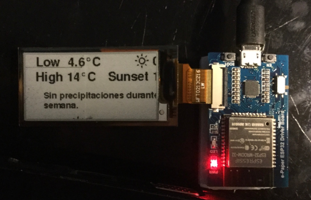
In my pursuit to make the CALE displays as small as possible but also to learn how different boards interact with Epaper I got last week an Waveshare E-Ink ESP32 driver board. Not all the boards need to use the default SPI GPIOs of the ESP32 and this was one of this cases. Opening the…
-
Hackaday projects update: CALE Eink Calendar and udpx
I must say although I’m not proud of all the projects I tried to document in Hackaday I do like a lot udpx and Remora, that are made initially to control Addressable LEDs, but they could be expanded and used for another uses. CALE This is actually an old project for the agency I work…
-
Cordova cross platform mobile applications
After the small Chrome App experience that resulted in a very compact app that reads Video and sends an UDP binary stream to ESP32 Led controllers I decided to start learning how to program a real mobile app. Real because I find that the way to do it must end in the App Store and…
-
Subscribe
Subscribed
Already have a WordPress.com account? Log in now.
