
Meet Remora-matrix a project that started with the idea to sniff MIDI messages and make simple visuals on a LED-Matrix. Our previous Firmware Remora was intended to receive short commands from ORCΛ and make very simple Neopixels animations on addressable LEDs stripes (WS2812B like)
With this one I decided to go a step further and make two versions, one that uses nodejs as a middleware (Requires WiFi and UDP) and other that uses MIDI serial, received directly via Serial2 (TX, RX) UART and hence requires no WiFi connection.
- NODEJS VERSION
This version uses a middleware script that sniffs a MIDI port (Ex. USB) and converts the messages into UDP messages that fly over WiFi to a destination IP. This script lives at the moment in middleware directory. An npm install needs to be run in order to install the required JS libraries.
cd middleware/midi-to-udp
nodejs midi.js
// Will list available midi entries. Requires port and udp destination IP
-p, --port_id  ID: Port name
                  0: Midi Through:Midi Through Port-0 14:0
                  1: USB MIDI Interface:USB MIDI Interface MIDI 1 20:0
                                                              [number] [required]
   -u, --udp_ip                                               [string] [required]

// EX. listen to port 1 USB Midi and forward them to UDP x.x.x.x:49161
// Port is fixed to the ORCA default port, feel free to update it  ^

nodejs midi.js -p 1 -u 192.168.12.109
This script will simply run in the background and redirect them using a simple short message that we designed to be compatible with both UDP and Serial versions.
2. MIDI SERIAL version
This uses the Sparkfun Arduino midi HAT that cost around 15 u$ and it can be found both in eBay and Aliexpress. The easy task is to build a connecting PCB below that hosts the ESP32 at the side of the HAT with the RX and TX cables from the HAT outputs connected to the ESP32. This HAT has an opto-isolator, also called octocoupler, that converts the MIDI signals into readable UART messages.
My prototype construction looks like this:
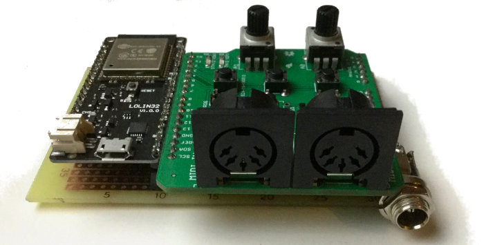
The MIDI Hat was designed for Arduino and requires 5 volts to run, so the 4 cables wiring is pretty straightforward:
HAT midi > ESP32
5v . . . . 5v
GND . . GND
RX . . . . 26
TX . . . . 27
I’m quite sure the TX goes to TX in the ESP32 but may be also the opposite. There is no standard for this I think. But in case it does not work just invert it, there are only signals, so you won’t break anything for trying this. The advantage of Serial are that have less latence than WiFi. Depending on how clean your connection is, sometimes WiFi UDP packages can become clogged, and get out all together which is quite an undesirable effect if you are working with LIVE music. Also UDP nature is designed to be very fast, but has no order like TCP.
It’s possible that a note played comes in different order as expected. Or if WiFi is shared, that while your Router is busy, the packages will accumulate and then sent all together, causing a burst of shapes in the Matrix in a moment that does not correlate with the music. This is not happening with the Serial version since there is no middleware redirecting packages and it cam be run without any PC in the middle. As there are no flying WiFi messages, has less latence and it’s much more reactive and fun to work with. Being the only pitfall being that you need a MIDI cable from your computer or Synthesizer to the MIDI Hat + ESP32 controller.
Most LIVE music lighting equipment does not rely on WiFi and there is a good reason for it!
Reliability.
Building our own internal Midi messaging system
Since this two versions want to achieve the same goal, that is converting the MIDI played into shapes, I though to create an internal messaging that is shared. Maybe this can be a C++ class or component in the future so it should speak the same language, no matter what version you use. The result is very simple, we will keep Channel internally and will use only Note + Status + Velocity.
Status and Channel come in the first byte. Then comes the Note and at the end the Velocity. Once we get the last byte, we will assemble this with the following syntax:
2 chars (HEXA) representing Note played1 boolean representing Status (1 note on, 0 note off)2 chars (HEXA) representing VelocityNNSVV Note, Status, Velocity Example: Playing DO in octave 3 that is 36 in decimal, velocity 60, Note ON message would be:2413B When the same note is released it could be: 24000
After building the message the channel is analyzed. It can either hear on all channels leaving the constants in platformio.ini to 0. Or hear in 3 different channels (Also 3 instruments) this can be of course modified, but 3 is a good balance, to see something that can be correlated with the music. The configuration for this is on platformio.ini file using build_flags
   -D SERIAL2_BAUDS=31250
   -D RXD2=26
   -D TXD2=27
   -D MIDI_LISTEN_CHANNEL1=1
   -D MIDI_LISTEN_CHANNEL2=2
   -D MIDI_LISTEN_CHANNEL3=15
   -D MIDI_FIXED_VELOCITY=0
   -D MIDI_BASE_OCTAVE=4
   -D MIDI_TOP_OCTAVE=12
There you can see that this will only forward packages for channels 1,2,15 all the rest will not be sent to the matrix.
There is also an option to ignore Velocity and use a fixed number ( MIDI_FIXED_VELOCITY )
And depending on the song, it could played on a high tone, or in a lower tone. Because our matrix is limited, we need to define BASE_OCTAVE and TOP_OCTAVE so we can have a drawing range.
That is the most important midi configuration. It would be desirable to have a “learning phase” where you can simply hear the first 10 seconds of a song and calculate this BASE and TOP margins automatically. This a future idea that might be implemented.
Interpreting the messages
I left just a demo of how to interpret this in C++. As we have 2 different firmware versions, one that listens UDP messages, and another one that get’s MIDI via UART you have to select what to compile editing platformio.ini File:
[platformio]
default_envs = esp32
# Uncomment only one of the folders to select what example to run:

#src_dir = firmware/udp-midi-matrix
src_dir = firmware/midi-in-matrix
Every message at the end triggers a function that draws a shape. And that part is open to every different implementation. For example, you can draw a different shape per channel, like:
Ch1 – Usually piano or main instrument – Rectangles
Ch2 – Triangles
Ch3 – Circles
Ch4 – Lines and so on
As said this is just an example, but it’s open to draw anything you want, since we are using GFX over the RGB Led matrix. Also you have the Velocity, that is the pressure that is applied to the key, so you can use this factor to make the shape bigger or change colors. The possibilities are unlimited.
There is only one important thing to keep in mind. A note with status 1 should be drawn, but same note with status 0, signalizes that the key was release hence we should delete the shape.
At the moment is just an experiment that will may never see the light out of my studio, but nevertheless I wanted to leave this post as a declaration of intentions, in case someone wants to fork this and make his own take.
Credits go to this awesome libraries
| https://github.com/marcmerlin/Framebuffer_GFX.git |
| https://github.com/FastLED/FastLED.git |
| https://github.com/marcmerlin/FastLED_NeoMatrix.git |
I writed to Marc Merlin who did the amazing job of adding GFX to FastLED and here I wanted to quote his answer
About FrameBuffer GFX: The good news is that your code will now run mostly unmodified on other displays like LCDs, or RGBPanels, or even display on linux.
Marc
Like this you can write all your code, run it, and debug it on linux, and then upload it to ESP32 or rPI when it’s done.
After that, you can go big!
