-
On driving Eink displays
There are 2 different known ways to drive them that are widely known:– SPI epapers, can be driven with this popular interface that is supported from Arduino, to a wide variety of MCUs– Parallel epapers also called einks like the ones that are used in Kindle & another e-readers Let’s start with the most easy…
-
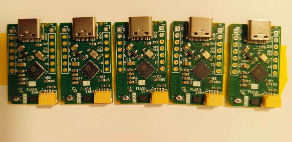
External Flash IC test on ESP32C6
In last board we send to fabrication the C6 ULP project I’ve failed miserably. Why?The board routing and schematics was Ok! But I’ve wrongly mistaken the ESP32C6 MCU using a 40 pin QFN that does not come with built in flash.You can find the open source KiCad files in this repository.Sadly that is the bad…
-
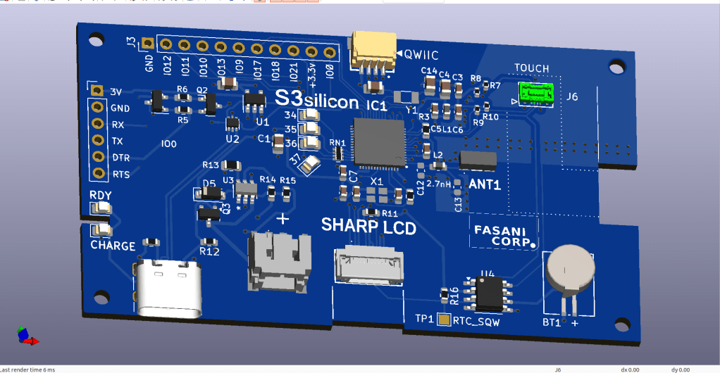
SHARP Controller LCD based on ESP32S3
The evolution of a simple C3 controller board into a full fledged ESP32S3 “Silicon only” small PCB that can control 400×240 LCDs and all their smaller models.First LCD controller I designed was a small clock size 128×128 pixels sharp LCD inspired by my friend Larry Bank who also likes this display technology. The evolution that…
-
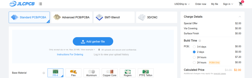
Sending boards to fabrication in JLCPCB using their PCB Assembly service
In this entry we are going to add some instructive videos on how we prepare fabrication files in order to send them to fabrication in JLCPCB using their PCBA service. In this 3 videos I show what is my personal approach to prepare fabrication files to send a PCB design to JLCPCB. Including the BOM…
-
Making an epdiy v7 Kaleido clone – Routing – part II
In Part I of this series we described how to take an existing KiCad open source repository, fork it, and start making updates to customize the PCB.This PCB will be ultimately sent to fabrication using our trusted service of JLCPCB using their PCB Assembly service. My mission in this PCB project is to make a…
-
Making a epdiy v7 Kaleido clone – part I
In this post we are going to clone the epdiy v7 Hardware repository and make a custom version to control a Eink Kaleido 6 inches display.The existing epdiy v7 can control this epaper already but we want to make a PCB clone specifically for this display, removing other connectors and adding additional ones for Touch…
-
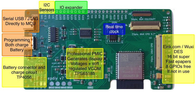
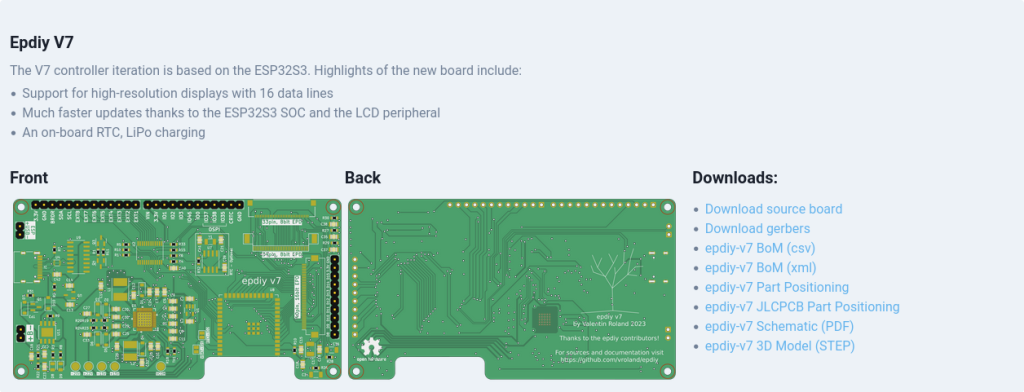
epdiy V7 S3 parallel epaper controller
I wanted to announce that the hardware for epdiy version 7, latest hardware for the project designed by Valentin Ronald, is ready to be tested. The original hardware you can find in the s3_lcd branch, this is my custom modified V7, that exposes 3 connectors: (Now already merged in main branch) I’ve been testing also…
-
New cases for the 9.7″ parallel displays and proposal for CLB Club
This might be a continuation from the Cinwrite DEXA epaper controller that we designed just after partnering with Freddie from Good-Display.comThe idea is to prepare an open source Firmware that is ready to be used with different examples and two target controllers: 1 – DEXA-C097 from Good-Display needs additionally my Cinwrite ESP32-S3 SPI controller Optionally…
-

Testing touch on small SPI epaper displays
Our now IDF ver. 5 compatible touch component FT6X36 is ready to be tested. There are two affordable models that I would like to cover in this post. First one is the 400×300 FT6336 from Good Display, we can see this one in action (2nd video, 1st had still wrong Waveform) It’s important to know…
-
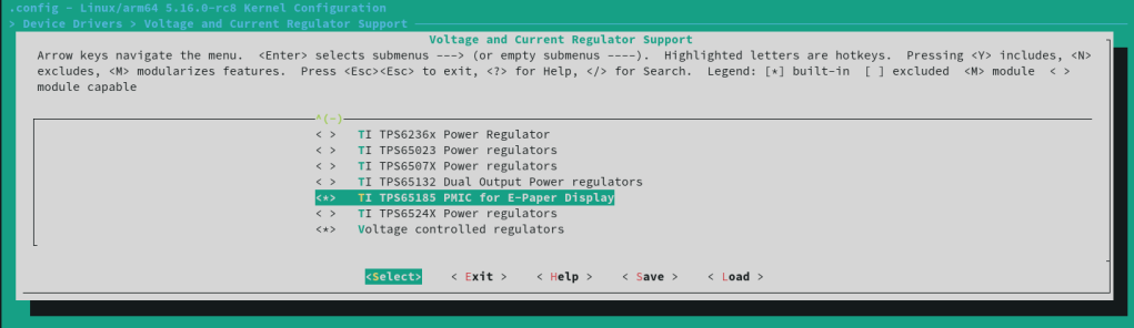
Compiling an ARM Linux kernel with EBC eink interface
First of all the essentials which are clearly explained here: Build your first Linux kernel and make sure you have at least 8 GB free disk space .Please be aware that building your own Linux kernel needs to be done with care and it’s a risky operation where you might need to wipe everything if…
-
Subscribe
Subscribed
Already have a WordPress.com account? Log in now.
