The evolution of a simple C3 controller board into a full fledged ESP32S3 “Silicon only” small PCB that can control 400×240 LCDs and all their smaller models.
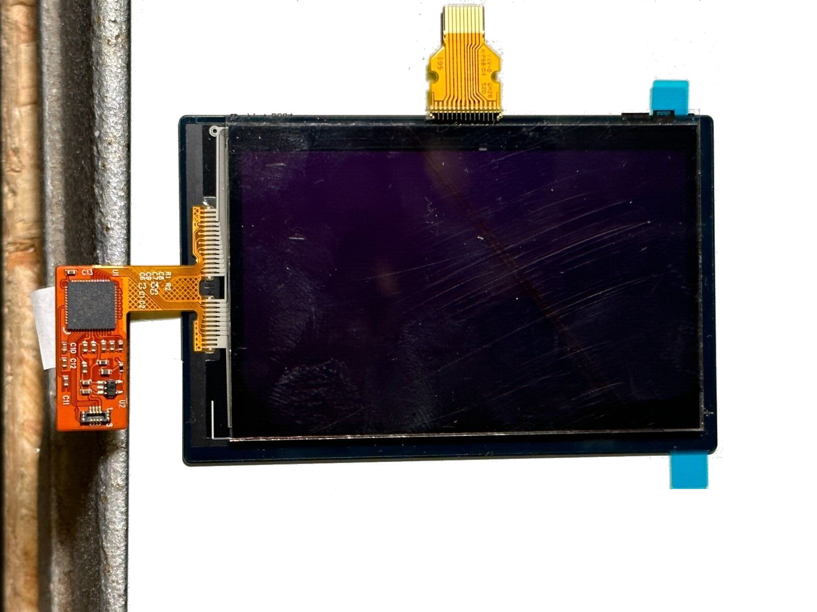
First LCD controller I designed was a small clock size 128×128 pixels sharp LCD inspired by my friend Larry Bank who also likes this display technology. The evolution that I never sent to fabrication was a bigger model to be the master controller of a 400×240 memory LCD that you can see in this picture:
This had already the idea to add an optional 2.7 inch touch layer however I never send it to fabrication since it’s a silly idea to add a touch overlay if you don’t assemble it professionally. For those who do not understand the industrial process of attaching a touch overlay to a display, is done with special machines that use the OCA method:
Optically Clear Adhesive (OCA) improves the brightness and contrast of a touch screen. It allows a clearer and more vivid user experience.
UPDATE: Here you can see the latest Rev. 1.1 of latest PCB with RV3032 RTC and IMU ready to make the weareable gadget of your dreams
https://www.tindie.com/products/fasani/s3-sharp-lcd-controller-wtouch-rtc/
This is the only way that a touch get’s a professional look without any “bubbles” or shadows between the display and the touch. So I simply put the project on hold until one day someone pointed me at this in eBay:
So the guy is now selling this in eBay to recover part of the money. I had to make a PCB since it was the perfect opportunity to make a cool gadget and learn a bit more in the process.
There was a problem though: A quick search of Mxt144 didn’t bring any known C embedded library. But luckily there are some friends around like Larry with it’s long experience doing C libraries for displays and capacitive touch that come to the rescue. I’ve got 2 units in eBay and quickly found a way to wire some test-pogo cables to test the touch. It worked out and I could see the 0x4A coming in the I2C scan but I could never initialize it correctly. Larry did!
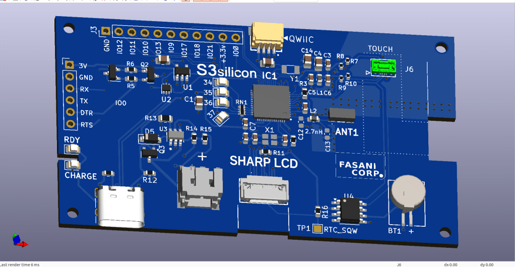
That was all I needed to design the PCB. But this time I wanted a smaller form factor, so I was not going to use the ESP32S3 module. I started from a previews design that worked perfectly as expected except the RF tunning that I don’t really know how to do, and had to remove the tunning capacitors near RF antenna, in order to get WiFi working.

This was my first small PCB that used S3 silicon. No PSRAM and the part used is: ESP32-S3FN8 https://jlcpcb.com/partdetail/EspressifSystems-ESP32S3FN8/C2913196
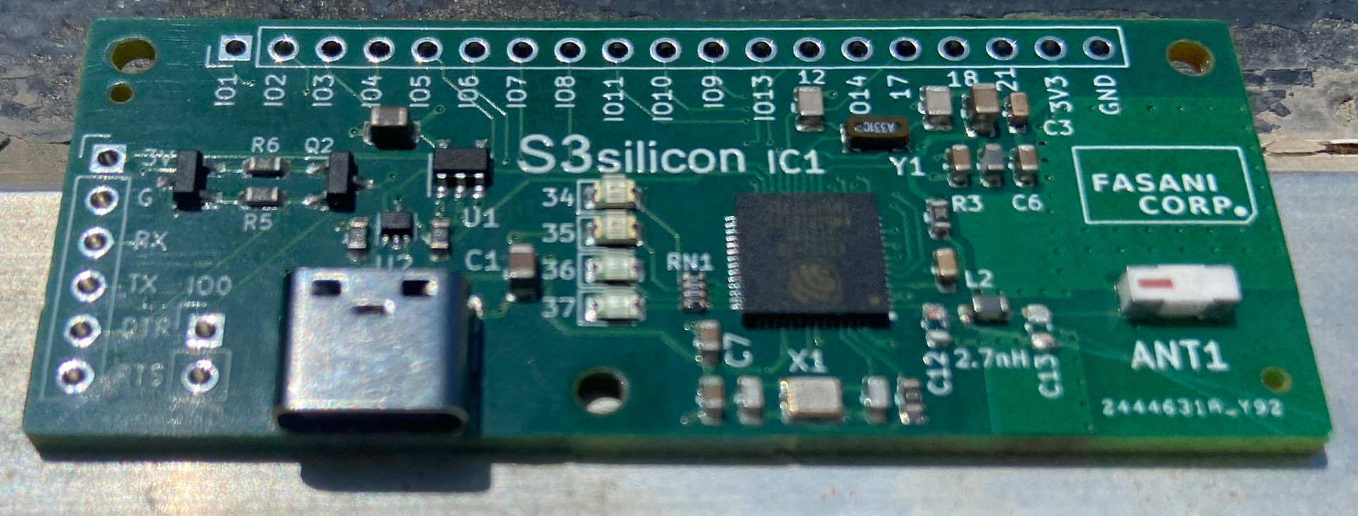
As you can see there is a basic circuit you need in order to flash the Chip, using no UART, but only the built in USB. And you also need to additionally make the Download circuit using IO0, making UART headers, since you cannot trust that the Microcontroller will accept always built in USB programming (For example, you make a deepsleep loop, then it’s bricked) In some situations you will need to flash it using UART.
And then following Espressif ESP32-S3 design guidelines, you need to add two Crystals, one is for the Chip itself in my design: Crystal 40 Mhz 10ppm. And an additional one that is for the ULP processor, for example, when you deepsleep only a few seconds. Then that second Crystal is the one that counts the cycles, when all the rest of the circuit is in low consumption mode. I’ve no idea if all of this was done 100% in accordance to the design guidelines but I certainly read the important parts a few times.
That small PCB was a success and I could test all of it. The only thing that failed was the Antenna tuning: C13 and C12 had to be scraped away in order to get WiFi.
RF is really an additional layer in electronics that only a few wizards can master. You need specialized measurement tools that not everyone has in his studio plus you need the knowledge to use them and a vast comprehension on how RF works. That’s the reason only a few developers like Seon the unexpected maker, and professional companies like Makerfabs and Seeed, make WiFi boards that are Silicon only. All the rest of us need to use Modules that come with RF Antennas built in and most importantly “tuned” and balanced, to have the best possible performance.
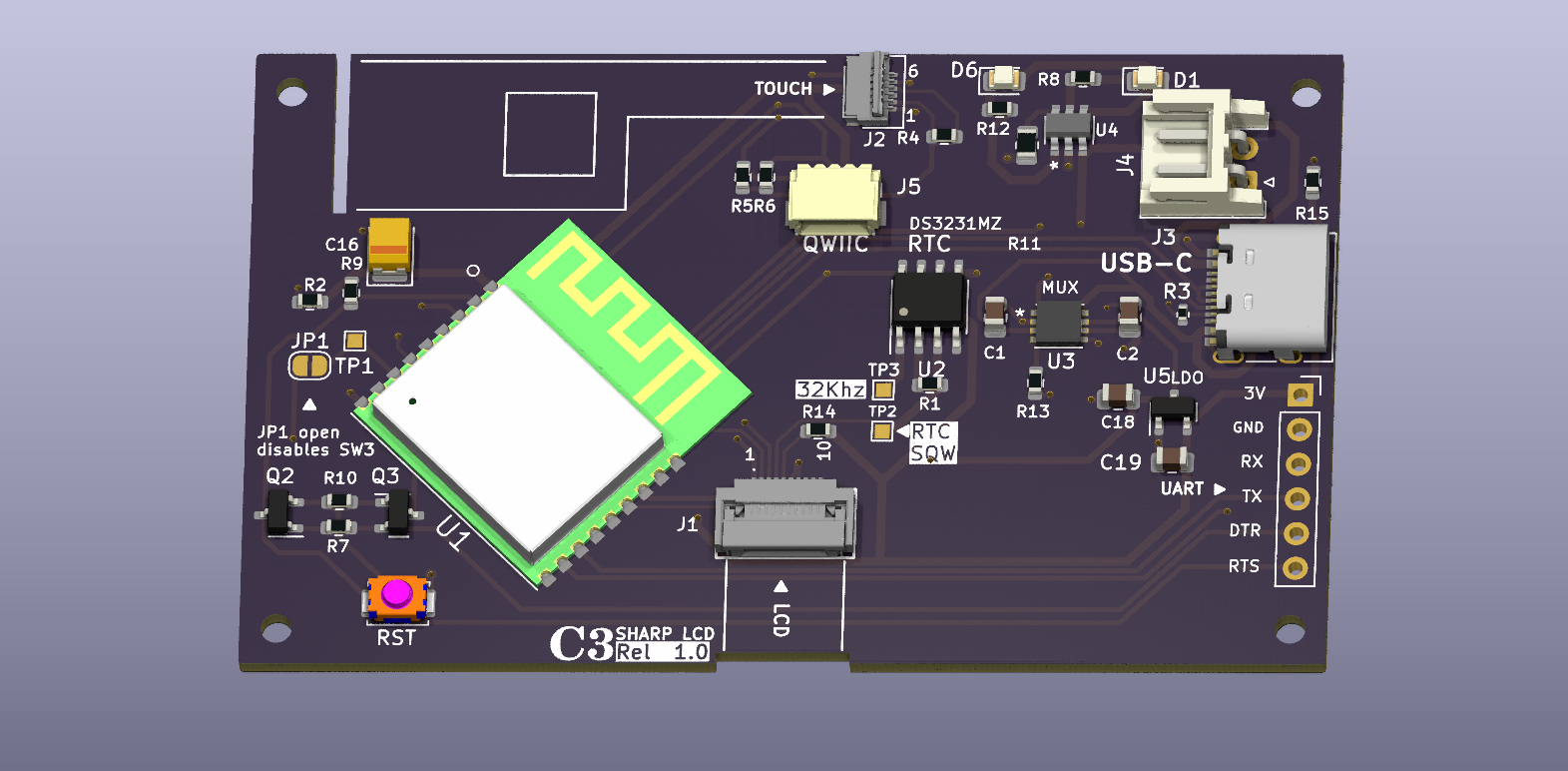
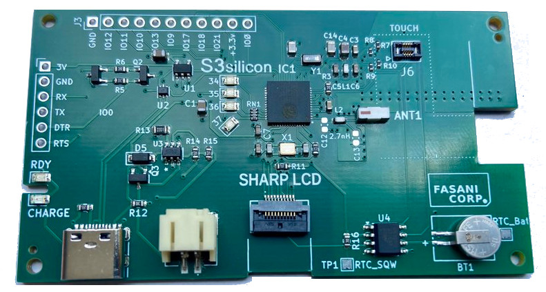
Based on that previously working design this is the new board that is also open-source and you can find here: https://github.com/martinberlin/Sharp-LV

On first revision I failed on the lower pins of touch that is reversed (Marked in green). I had to swap I2C pins to make touch work. But other than that this board has a few features that are ready for low consumption:
– LCD DISPON is pulled up to 3V3 allowing the display to work when all the rest sleeps
– LCD VCC is coming from battery power or from 5V allowing the SPI to work at it’s fastest speed (And also when all the rest is sleeping)
– RTC is also powered when the rest sleeps so the Squarewave can still go to the LCD. And it has a small LiOn battery to keep it churning that you can see in the lower right part.
In resume is though to make the most out of the LCD even when the micro-controller sleeps. And is already corrected in the repository, so the touch pins, now are correctly routed.
The first version of this display controller is now for sale in Tindie Flea-Market so I can collect some funds to make the second revision. At 19 USD it might be the low cost LCD controller to experiment sending to production that weareable widget you always wanted to have!
Instructions for those who want to repair the touch:
Not recommendable if you have heart related issues.

The idea was to sell this PCB as LCD controller only but with this small reparation touch works too:
- 1 Enable power in the touch (short R8)
- 2 Swap RTC I2C wires (Now SDA is clock)
- 3 Cut 2 mm off the PCB on the right (Where FASANI CORP logo is)
No worries there are no traces under that part. - 4 Careful with the touch as you can see is 2 mm wrong positioned!
IMPORTANT: Shorting R8 you are also feeding GPIO 5 (Used to be Touch RST) with 3V3 and that will consume additional 100 uA on deepsleep. There is no way to cut the trace since it goes in one of the middle 4 layer sandwich.
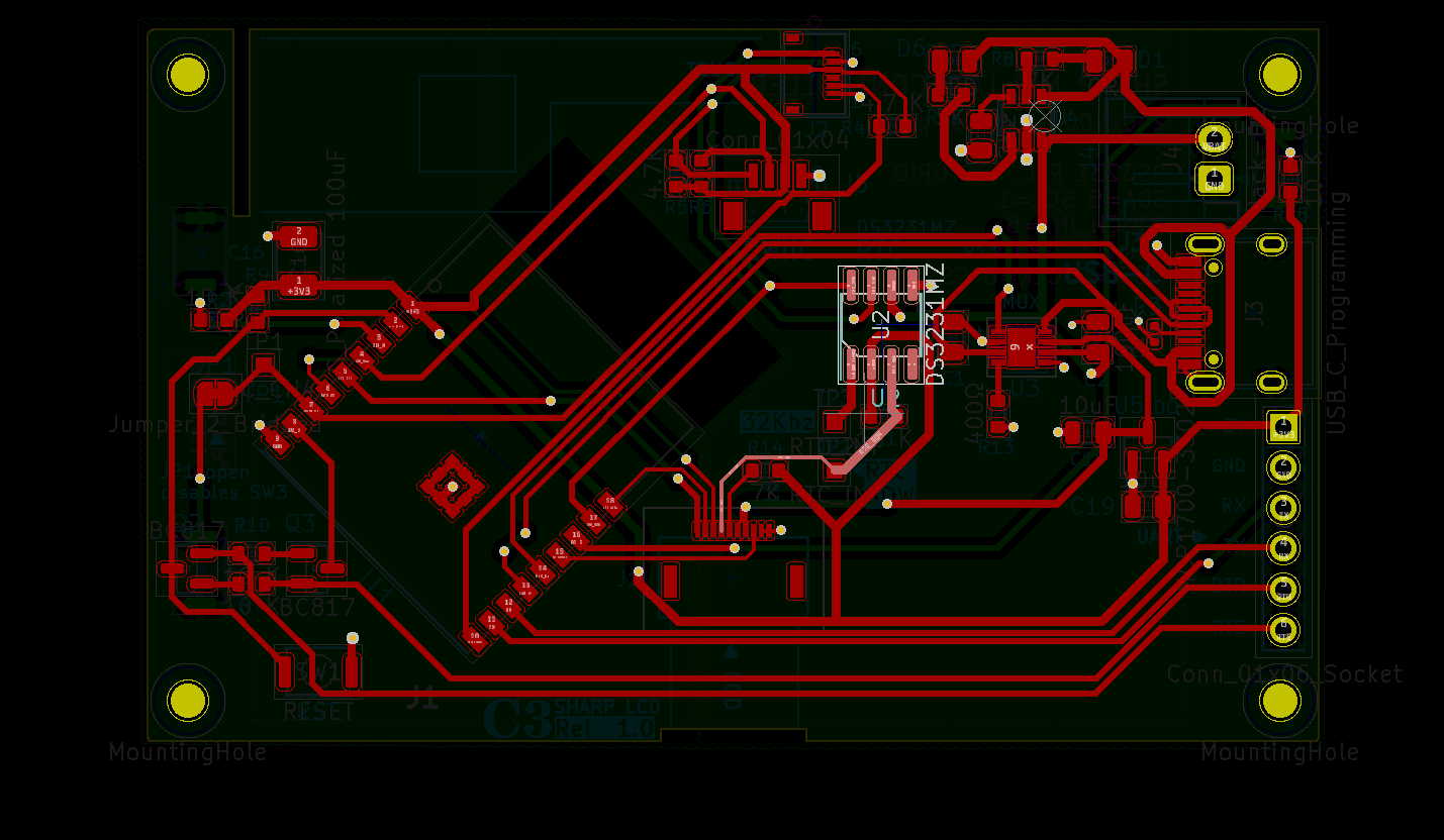
Please find Schematics (Rev 1.0) and full Kicad project here:
https://github.com/martinberlin/Sharp-LV/tree/main/S3-silicon-Sharp-Touch
Now if you want to get last revision that has the touch repaired, please get Rev. 1.1 with RV3032 RTC and IMU ready to make the weareable gadget of your dreams
https://www.tindie.com/products/fasani/s3-sharp-lcd-controller-wtouch-rtc/
If you like our work and publications there is a chance you like our PCB products. Please visit our Tindie store and check if there is something that can inspire you for your next projects.
