The idea of using a HM3301 Laser dust sensor was to make a data representation that instead of boring numbers show a more visual appealing image representing particles and their size.
For that we though about making a read each 2 minutes and use a bi-stable display with 4 grays.
Components used:
- Seeed HM3301 I2C sensor
- GDEW042T2 400×300 epaper display and a SPI adapter DESPI-CO3
- Custom 3D printed case you can find in Thingiverse
The build work!
First you should measure the ESP32 board that you are going to use. Same we did with the HM3301 sensor 3D Model and we also uploaded it to Thingiverse.
That way it’s easier to place in the 3D design and move the small holders with 2mm holes (for the screws) to secure your board. You know, when you start using hot glue everywhere, is when it starts lookin’ bad :)
For that reason we provided the Blender file so you can use a free 3D modeling program to move things around as you like. Then you can simply switch to Wireframe view with key Z select with B (Bounding box) all what you want to export and export to STL.
This small article is focused on the build and Blender itself is a tool that is not for the faint of the heart, but is a nice and powerful 3D program, that in my case made sense to spend days learning how to tinker with it.
After 3D printing the bottom case you can start placing the parts. But it makes a lot of sense to test all this outside the box first, so first we need to connect the sensor that is easy since it’s 2 wire I2C (Plus power and SET pin, that on low makes the sensor sleep)
# Default I2C (No need for pull-ups are already in the sensor)
CONFIG_SCL_GPIO=22
CONFIG_SDA_GPIO=21
# Note we use 14 but could be any output PIN
HM3301_SET_GPIO=GPIO_NUM_14
With those in place we should be able to already flash a program and check the measurements. Please note that SET pin should be on HIGH in order for the sensor to be powered on (Bring the small fan close to your ear, you should hear it!)
For that we created our HM3301 component since there was no ESP32 IDF component, you can find it here:
https://github.com/martinberlin/HM3301-idf
You can already link this as a submodule in the components folder or for an easier test, just download our epaper-weather-station project and their linked components using the develop branch:
git clone –branch develop –recursive https://github.com/martinberlin/epaper-weather-station.git
–recursive will also pull linked submodules making it really easy to have everything available at once.
Updating the main/CMakeLists.txt you can point the build process to the file you want to build as your main entry point. And in the main/tests directory we left an hm3301 test program.
If that goes as expected then doing a: idf.py flash monitor
You should see sensor readings in the Serial output.
Congratulations, your Dust sensor seems to be measuring particles.
Now let’s go ahead and connect the epaper display!
Make sure that you connect the SPI adapter DESPI-CO3 and secure it to the epaper with some nice tape. I’ve used also here 2 small spots of hot glue but is not recommended, you might damage that nice display (Although I didn’t since I wait some seconds until is not super hot and I apply 2 small spots)
The idea is just to avoid making force over the sensible FPC flexible cable.
Once that is done you can start the SPI + power wiring to the ESP32 board:
CONFIG_EINK_SPI_MOSI=23
CONFIG_EINK_SPI_CLK=18
CONFIG_EINK_SPI_CS=12
CONFIG_EINK_DC=19
CONFIG_EINK_RST=27
CONFIG_EINK_BUSY=33
That are IOs we used. For MOSI and CLOCK we usually use the ESP32 defaults. But you could of course use the GPIO matrix to route this signals to any output pins.
If all that is good connected and also the 3.3V and GND pins are perfectly connected, and tested with the multimeter that in fact are powering the epaper…then this should display something!
Just try our next example program:
https://github.com/martinberlin/epaper-weather-station/tree/develop/main/SPI-displays
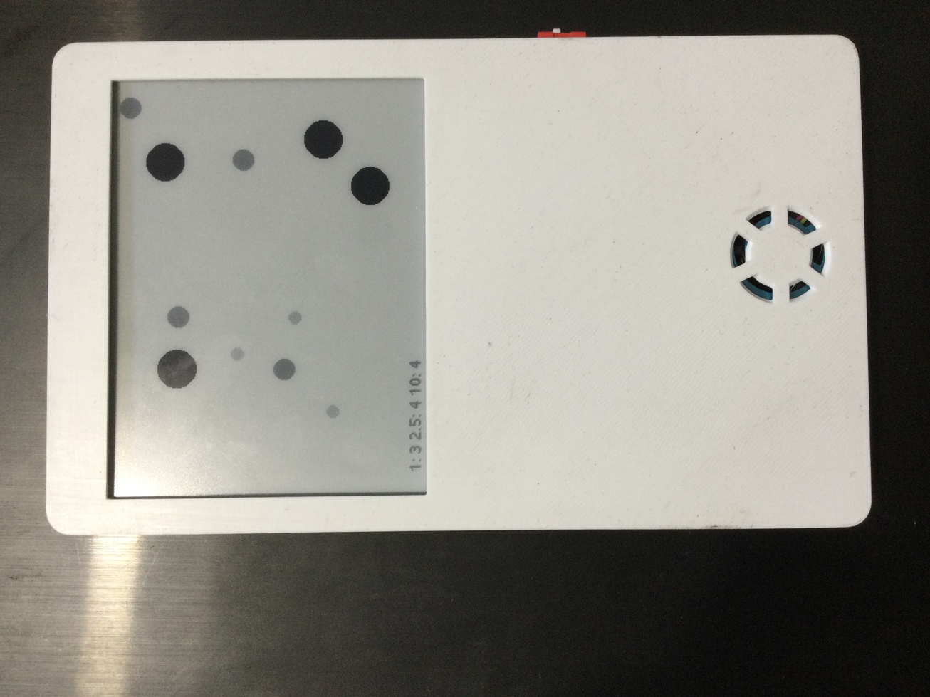
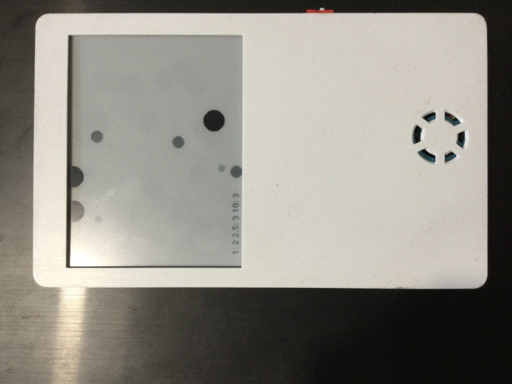
With particle-draw.cpp you can test a program that reads from HM3301 and displays some random circles showing how many PM1, PM2.5 and PM10 particles are there.