-
Making an epdiy v7 Kaleido clone – Routing – part II
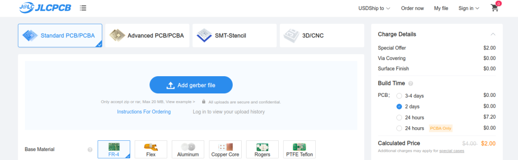
In Part I of this series we described how to take an existing KiCad open source repository, fork it, and start making updates to customize the PCB.This PCB will be ultimately sent to fabrication using our trusted service of JLCPCB using their PCB Assembly service. My mission in this PCB project is to make a…
-
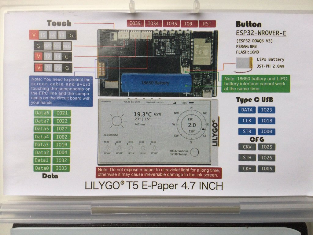
epdiy V7 S3 parallel epaper controller
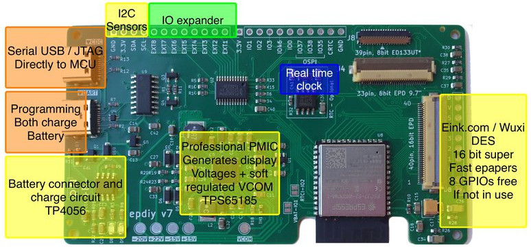
I wanted to announce that the hardware for epdiy version 7, latest hardware for the project designed by Valentin Ronald, is ready to be tested. The original hardware you can find in the s3_lcd branch, this is my custom modified V7, that exposes 3 connectors: (Now already merged in main branch) I’ve been testing also…
-
Dust sensor data representation
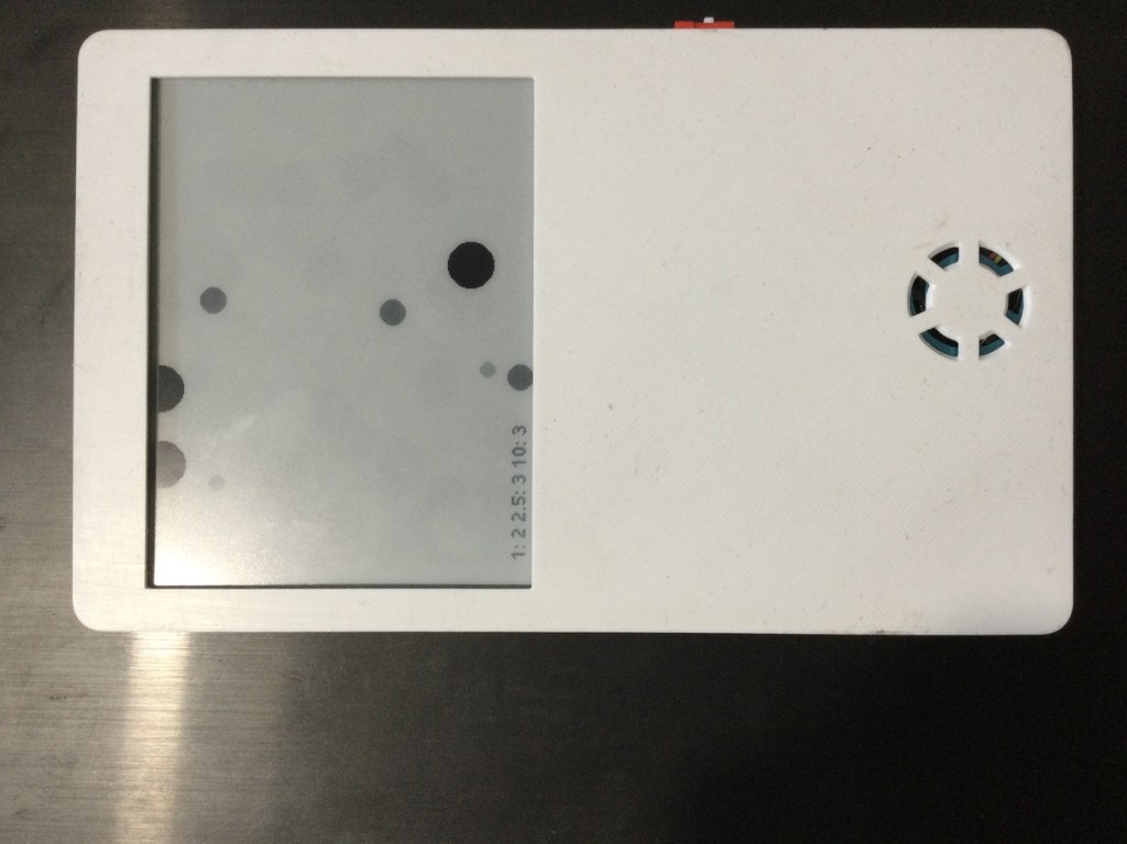
The idea of using a HM3301 Laser dust sensor was to make a data representation that instead of boring numbers show a more visual appealing image representing particles and their size.For that we though about making a read each 2 minutes and use a bi-stable display with 4 grays.Components used: The build work!First you should…
-
New Cinwrite SPI HAT for IT8951 parallel epaper controllers
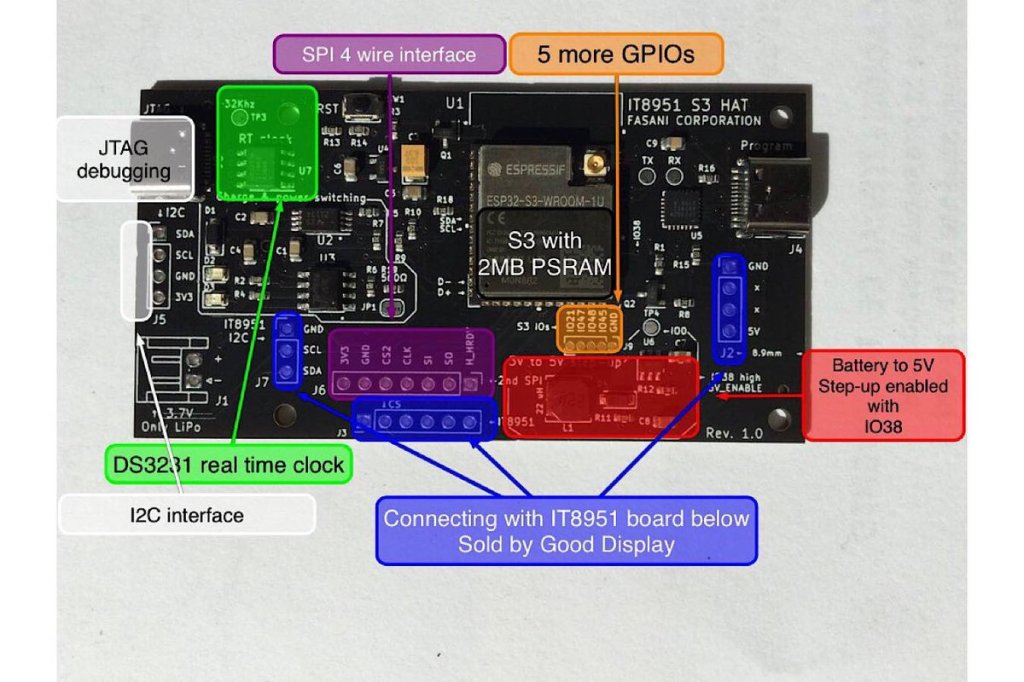
At the moment only available in Tindie Fasani Corporation store this PCB mission is to provide: This Cinwrite PCB is open source Hardware that you can explore and even adapt to your needs. The price is 45 USD since I only made 5 and otherwise it will be impossible to cover the costs. But it…
-
LVGL to design UX interfaces on epaper
lv_port_esp32-epaper is the latest successful attempt to design UX in C using Espressif ESP32.If you like the idea please hit the ★ in my repository fork.What is LVGL? LVGL stands for “Light and Versatile Graphics Library” and allows you to design an object oriented user interface in supported devices. So far it supports mostly TFT…
-
Using WiFi epapers to showcase digital art
Recently I stepped upon superrare.co that is a marketplace to collect and trade unique digital artworks. This and the fact that I follow Josh Katzenmeyer that is a member of this network made more aware of the fact I enjoy watching this artworks very much and got me interested about it. My idea is very…
-

New epaper component for ESP-IDF
E-paper component driver for the ESP-IDF framework and compatible with ESP32 / ESP32S2 can be found in this repository: https://github.com/martinberlin/CalEPD Codenamed Cal e-pe-de for the initials of E-Paper Display this is basically all what I’ve been doing the last weeks. Learning more about C++ object oriented coding and preparing a class that can be used…
-
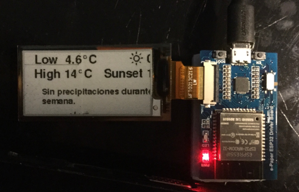
Trying out Waveshare E-Paper ESP32 driver board
In my pursuit to make the CALE displays as small as possible but also to learn how different boards interact with Epaper I got last week an Waveshare E-Ink ESP32 driver board. Not all the boards need to use the default SPI GPIOs of the ESP32 and this was one of this cases. Opening the…
-
Reading an image bitmap file from the web using ESP8266 and C++
There are a couple of different ways to do it, but I wanted to do it after a simple image example, to understand a bit better how reading a stream from the web to get as far as the pixel information and send it to a display. As a reference then I started with ZinggJM/GxEPD…
-
Subscribe
Subscribed
Already have a WordPress.com account? Log in now.
