
This is the resume of the previous entries where we custom modified epdiy version 7 into a custom PCB to control initially a Eink Kaleido display. In latest release we also modified slightly the Schematics to add a second touch model: TMA340 / TMA445 that is often found in the Kindle ED060XC3 also codenamed paperwhite 1(or 2) depending on the release year.
The start phase of this project was when a client wanted to control Eink Kaleido 6″ display. This used the standard 34 pins FPC and had also touch plus front-light.
The initial push to add Kindle display support was that all the 34 pins 6 inch displays share the same pin-out, so the display controlling was already resolved with the Kaleido version. The difference is that Kindle display at about 32 USD is much cheaper compared to Kaleido that costs about 200 USD. It’s an older 16 grayscale capable display but for me was a nice challenge since it had a touch that is undocumented and end of lifetime: TMA340 from Cypress.
Talking about this with Dario Budimir in the epdiy Slack channel he liked the idea and helped me to reverse-engineer it. Actually he started the base program and I2C boiler-plate code that already exists in the LVGL driver.
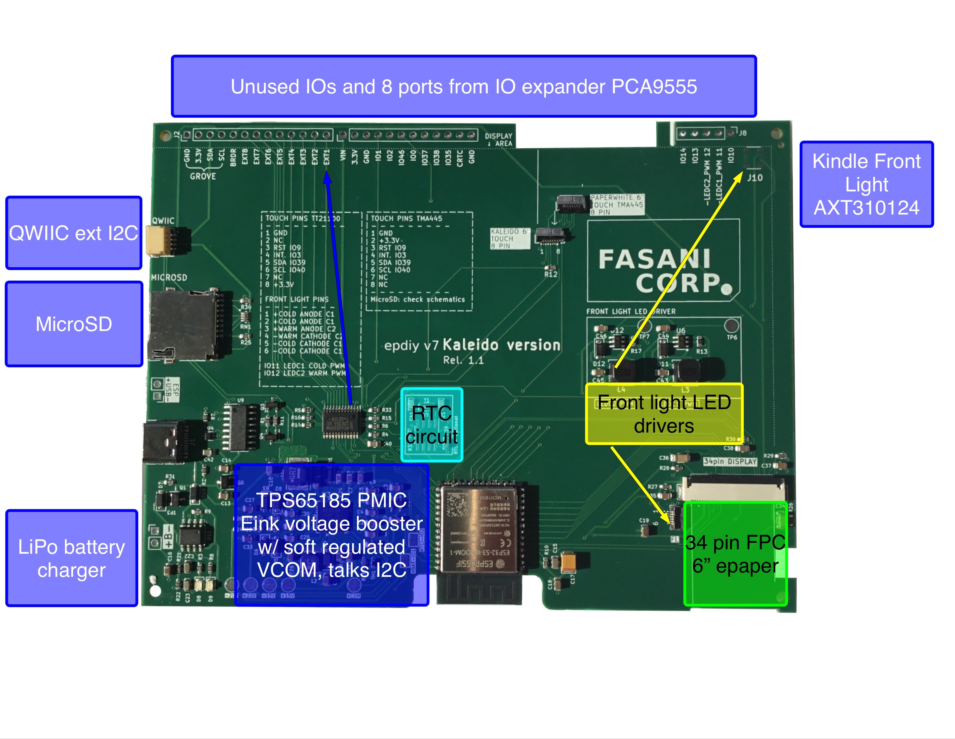
Reverse engineering the touch was a sprint of two days and about a week of small corrections and fine-tunning. I’ve no idea if it’s the optimal driver, I’ve just know that the X,Y and Z (pressure) of the touch seem about right. And that’s enough to use it as the input driver. Once the touch was proved to work I edited release 1.0 of the PCB in KiCad and added an additional 8 pin FPC connector. Sadly not in the ideal position, it’s displaced 1 mm to the right, in order not to invade the other (kaleido) touch.
That was not the wiser decision. It’s hard to make a PCB that supports two different displays, let alone 2 that have different touch and front-light connectors, and the only thing in common is the 34 pin display connector.
Reverse engineering the touch
Version 1.0 of the PCB had already touch on top of R12 up there in the photo. But it is designed for the Kaleido pin-out which is different than the Kindle display. Also it’s placed different as you can see in the top of our logo.
But before even planning to add it in the PCB the task was to see if it worked. After two days fighting and sorting out the pin-out after a bit of research online, I commented this to Dario ddB0515 and he helped out with the process of talking I2C with the input device. I did my part just transforming what it was a Linux driver into an Espressif IDF component.
The core of the issue when doing this kind of things is that you start with an information void that has to be filled. A touch device, in this case some version of STM32, that needs an initialization otherwise it won’t even react to anything. And you don’t have Datasheet. Dario tried to contact Infineon, who bought Cypress the original manufacturer, and they replied “We don’t offer support for End of Lifetime devices that are not produced for more than 2 years”. Another delicate way of saying:
“We have the Datasheet but we won’t bother moving our mouse to open that old folder and attach it to the E-Mail” Thanks it doesn’t matter we understand Infineon that corporate policies should be so tightly implemented ;)
Thankfully slowly sending commands after checking the Linux driver the touch started to wake up until finally we could see the X: 100, Y: 100 Z: 13 (Z is pressure) printed out of the serial!
Touch working let’s now add it in the PCB
At that moment it was just placing an additional 8 pin FPS connector in the Schematics as first step and then to add it in KiCad PCB designer. This is how it looked:
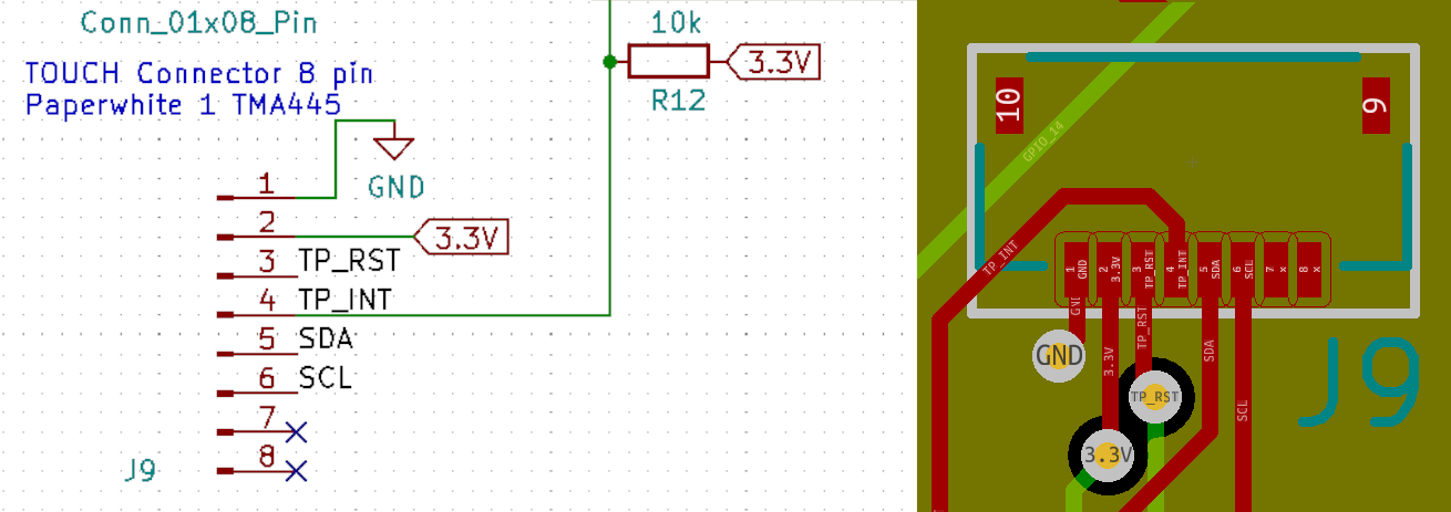
One key detail is that if you need an external pull-up like in the INT (interrupt) signal that is active low then it should be tested in the breadboard first. In case you are not 100% sure if it will need a pull-up / pull-down resistor anywhere in the PCB just let a 0603 or your footprint of choice empty and then you can just solder one resistor without adding wires all over. In first revisions, unless you are a genius that I’m not, you will always have some bodge wires around and that’s OK! We all make little mistakes here and there, in life, and when designing electronics!
Adding a LED driver for the front-light
In this part my colleague Dario helped and after seeing the 17 V booster design he told me: Man why don’t you use a LED driver for gods sake?
A LED driver is a nice IC that just manages the LEDs by limiting current. Just like most of the LED lamps at home do. No matter if you have 5 LEDs or 8 LEDs it will adjust the current automatically leaving you a pin to control the PWM duty. That’s nice right?
No more self made booster needed when you can just solve the problem with a dedicated and cheap IC driver like RY3730:
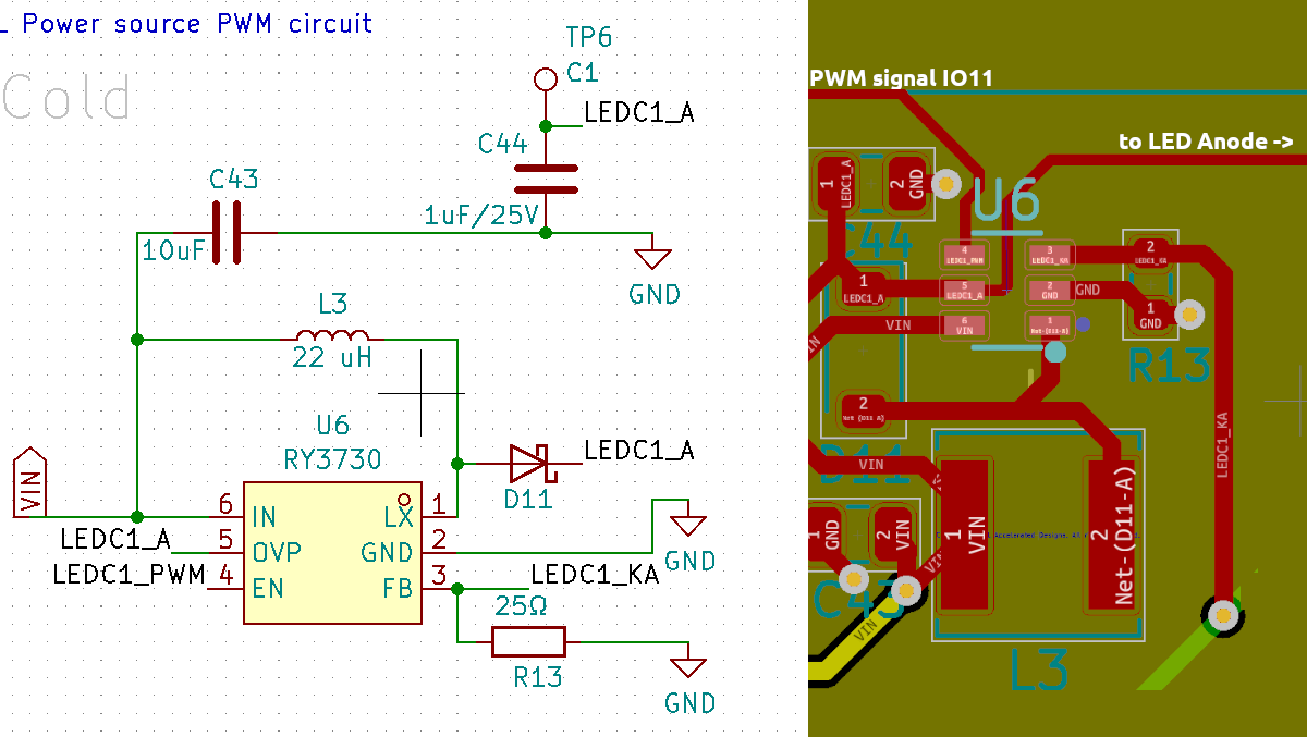
This had a small design error: When you add a PWM control to a ESP32** GPIO, you need to make sure this particular IO does not toggle state when flashing or when the CPU starts. And IO11 does. But not only that one, many others too, so doing this if Front-light is connected you will have full power flashes during flashing and boot of the CPU. This situation is easily solved just adding an additional Resistor pull-down to GND. And guess who forgot to add it in the PCB having a new revision that still flash the front-leds when the MCU starts?
It’s not a big issue since you can add a pull-mode programmatically to the IO but is still a molesting issue that can be solved if you are careful in the design and make second revisions by another peers that are experienced and had this things coming up before.
With this two new features and the MicroSD module that can be actually a new post itself, the new revision 1.1 of the Kindle eink controller is working fully and you can already buy the finished PCB in Tindie.
If you like our work and publications there is a chance you like our PCB products. Please visit our Tindie store and check if there is something that can inspire you for your next projects.
