Serial parallel interface was developed by Motorola in the eighties and is the standard or short communication in embedded devices.
( on SS low camera communicates with master )
The data transmission is explained in detail in the Wikipedia SPI article. But basically is along this lines and we will add some code examples below:
- The bus master sets up the clock using a frequency supported by the Slave device.
- Master selects the slave device with a logic level 0 on the select line.
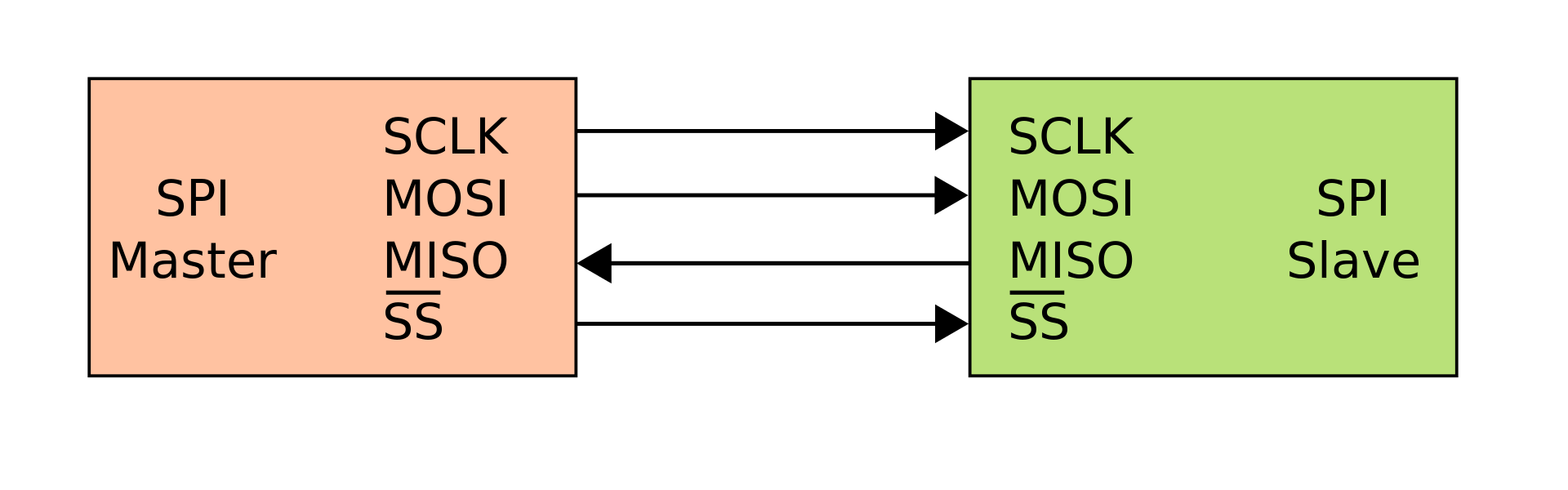
- During each SPI clock cycle a full duplex data transmission occurs. Master sends a bit on the Master Output Slave In line (MOSI) and the slave reads it. The slave sends a bit on the MISO line and master reads it.
That’s basically the essence of it. There is much more happening under the hood and it’s explained with more in detail on the referenced article. The interesting part of the SPI interface is that we can have many Slaves communicating with the master, since when the SS line is HIGH the slave ignores the master, so we can basically have a different SS (Or Chip select line) per device. So you can use the same Clock, Mosi and Miso to communicate with many SPI devices as long as the data communication happens with one device at the time.
The problem appears when you need to communicate with two different SPI devices at the same time
For example, in the WiFi Camera project, we made an experimental model with a st7735 small 128×128 pixels color TFT display that is also SPI. So if you want to make a progress bar in the moment where we are reading the Camera memory, you cannot use the same SPI interface, because you will share the data line and get a corrupted image.
Maybe there is a way to do it that I’m not aware of. When yes, then please add a code example ;) So my intuitive solution to the problem was to use a second SPI interface, completely independent from the Camera SPI. So that was a nice idea, but implementing it was not so nice, and the issue is that most of the libraries instantiate SPI like this:
SPI.begin(TFT_SCLK, TFT_MISO, TFT_MOSI, SS);
Or simply:
SPI.begin(); // To use default GPIOs
At this point we could make a stop and mention that the ESP32 has some custom SPI gpios that are by default used when you do an SPI.begin() without any values. And that is very well explained in the Espressif documentation for SPI master driver:
IOMUX pins for SPI controllers are as below:
| Pin Name | HSPI | VSPI |
|---|---|---|
| GPIO Number | ||
| CS0* | 15 | 5 |
| SCLK | 14 | 18 |
| MISO | 12 | 19 |
| MOSI | 13 | 23 |
So if I understand well and you see the GPIO writings on most ESP32 boards SPI.begin() without parameters starts the interface using the VSPI gpios also 18,19 and 23. But what happens if you want to use another GPIOS ?
No problem, just start SPI.begin() with the GPIOs you want to use. That as long that you don’t need to use a second SPI device. Because when you are instantiating SPI at a global level, you are instantiating a class that will use that GPIOs for all your program. So the solution is to use two different classes and there is a very good example about this in the SPI Multiple buses example on Espressif repository.
The problem is many libraries have not considered the possibility of multiple SPIs
At this point I had a solution but I was still far away of implementing it. Arducam library is pretty old and I could say, not maintained for the future generations of ESP32 chips. Even the SPI instantiation has to be done outside the Lib although the SPI.transfer and so on are fixed inside it. Too bad. TFT st7735 is a very nice lib and well maintained so it lets you define your own SPI gpios in the configuration. So after some minutes of doubt I decided to recode the SPI functions of the Arducam and make them mine. So that is what I did, to recode the SPI functions, leaving arducam library as a minimal I2C communication lib and taking SPI to my own command. Not a big deal, just check what functions are in charge of SPI.transfers and so on, copy them to your own and replace this by your own implementation.
We start our own class in a global level:
SPIClass * hspi = NULL;

void setup() {
   hspi = new SPIClass(HSPI);

  //        sck, miso, mosi, ss
   hspi->begin(16, 0, 4, CS);
   hspi->setFrequency(4000000);  // 4 Mhz
}
And that is it. After this we will use this hspi for our camera communication, leaving the other SPI for the display. It worked out, after some minutes of tweaking and burning my fingers changing wires from one GPIO to another.
https://twitter.com/martinfasani/status/1078585069458075648

The development + testing is happening in this repository:
github.com/martinberlin/cale-idf
If you want to use this as a component in your existing project: github.com/martinberlin/CalEPD
