This is a modification we did to a Peggy2 led panel.

- JP1 y JP2 enable the “serial hack” (Map at the footer of this post)
The steps to follow if you want to try this:
- Install this program in the Peggy through USB using Arduino software. This little program is just a loop that renders in the led panel putting Peggy in “Serial mode”
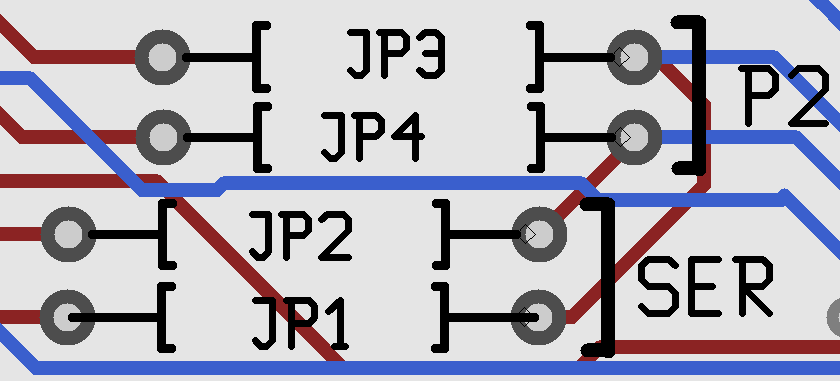
- Make the electrical brige like shown in the picture
Originally the bridge is from P2 to JP3 and JP4 so enabling Peggy2 to be programmed. To make this point clear, after changing the bridge you will not be able to install a program in Peggy, you will just send serial data through the USB - Download processing and try out programs designed to send data to Peggy
There are some examples at the end of this entry
This is the hardware modification explained by Carlos Fasani
Originally Peggy 2 has 2 bridges (0 ohm resistances) in jumpers JP3 and JP4.
With this connection the lines A_Sel and B_Sel of the multiplexor 74HC154 (U2) that controls rows 0 to 14 are connected to RXD (pin 2) and TXD (pin 3) of the microprocessor ATmega (U1).
But as this communication legs are needed to recevied serial data we take out JP3 and JP4 leaving the serial line desconected from 74HC154 (U2).
And then we bridge JP1 and JP2 connecting A_Sel and B_Sel from multiplexor 74HC154 (U2) to SDA (pin 27) and SCL (pin 28).
This way Peggy is ready to receive data and light the ROWS at the same time.
*UPDATE*
Windell, the Chief Scientist of Evil Mad Scientist replied to our email pointing out some important details that can be useful to make this even better:
It looks like you’ve run the two jumpers as follows:* First jumper: From the left side of JP2 to the right side of JP4, and* Second jumper: From the left side of JP1 to the right side of JP3.If I’m seeing this correctly, then your modification is exactly equivalent to putting the two jumpers in locations JP1 and JP2. (See the attached screenshot for verification of how this is wired.) And if so, you *should* still be able to reprogram the board, even after making the modification.
Thanks a lot for your clarification. I still didn’t tried this out since I forgot my soldier equipment but for sure it will work out.
Windell also pointed out that the latest Peggy 2 versions are already capable of receiving serial data and operating the full display at the same time, so long as you have the SER option selected on the board, and you are using our Peggy2Serial library and its RecvSerial.pde sketch
ATTACHED:
https://github.com/martinberlin/sketchbook
Electronic design of Peggy2 (pdf)
Jay’s projects. Jay was one of the first ones to send serial data and video to Peggy2
